
Steel Angle Bracket with Gussets: Shell Model Stress Check
Key result: under a $1\,\mathrm{kN}$ load on its base holes, the steel bracket deflects $0.14\,\mathrm{mm}$ and stays elastic: the peak von Mises stress is $185\,\mathrm{MPa}$, at the edge of the lowest bolt hole of the wall, an inverse reserve factor of 0.93 against the $200\,\mathrm{MPa}$ elastic limit.
SUMMARY
A linear static analysis of a steel angle bracket stiffened by two triangular gussets was performed in the finite element analysis (FEA) software Code_aster [ref. 1]. The bracket is bolted to a support through three holes in its wall and carries a $1\,\mathrm{kN}$ load through two holes in its base. It was modelled with thin shell elements (DKT) on its mid-surfaces: $5\,\mathrm{mm}$ thick for the base and the wall, $7\,\mathrm{mm}$ for the gussets. The reaction at the bolt holes balances the applied load ($1000\,\mathrm{N}$). The largest displacement, $0.139\,\mathrm{mm}$, is at the free edge of the base. The stress is highest at the edge of the lowest bolt hole of the wall, where the wall bends: $185\,\mathrm{MPa}$ von Mises, which gives an inverse reserve factor $\text{IRF} = \sigma_{VM} / S_y = 0.93$. The bracket stays elastic, with a margin of $7\%$ on the elastic limit. Away from the bolt holes, the stress stays below $84\,\mathrm{MPa}$ ($\text{IRF} < 0.42$).
INTRODUCTION
Angle brackets are among the most common parts in machines and buildings: they hold shelves, pipes, motors and panels on walls and frames. Two thin plates at right angles carry the load, and triangular gussets between them stiffen the corner. The question for the designer is simple: under the service load, does the bracket stay elastic, and where is it closest to yielding?
The bracket is made of plates much thinner than their other dimensions, so it is modelled with shell elements: each plate is represented by its mid-surface, and its thickness enters the element stiffness. A shell model needs far fewer elements than a 3D solid model of the same part, and it gives directly the membrane and bending stresses that govern thin plates. Following a rigorous sequence of steps, defining the geometry, the mesh (a discretisation of the geometry), the materials and the boundary conditions, the study computes the displacement, strain and stress fields of the bracket, and checks the stress against the elastic limit of the steel with the inverse reserve factor (IRF).
METHODOLOGY
The bracket is modelled with thin shell elements on its mid-surfaces. The mechanical behaviour is assumed to be linear and elastic, respecting the small strain hypothesis.
Figure 1 represents the general setup of the problem. The bracket is made of a base plate (in the plane $z = 0$) and a wall (in the plane $y = 0$), both $100 \times 100\,\mathrm{mm}$ and $5\,\mathrm{mm}$ thick, joined along the edge $y = z = 0$. Two right-triangle gussets, $7\,\mathrm{mm}$ thick, connect them in the planes $x = 33.3$ and $x = 66.7\,\mathrm{mm}$; their legs run $66.7\,\mathrm{mm}$ along the base and along the wall. The wall has three bolt holes of diameter $10\,\mathrm{mm}$, centred at $(x, z) = (33.3, 83.3)$, $(66.7, 83.3)$ and $(50, 33.3)\,\mathrm{mm}$. The base has two holes of the same diameter, centred at $(x, y) = (33.3, 83.3)$ and $(66.7, 83.3)\,\mathrm{mm}$.
The boundary conditions are the following. The edges of the three wall holes (group FIXED) are clamped in all six degrees of freedom: the three displacements and the three rotations are zero, which represents bolts holding the wall rigidly on its support. The edges of the two base holes (group LOAD) carry a total force $F = 1\,\mathrm{kN}$ along $-z$, spread uniformly along the hole edges. The polygonal hole edges of the mesh are $62.77\,\mathrm{mm}$ long in total (40 segments per hole), so the line force is $q = F / 62.77 = 15.93\,\mathrm{N/mm}$. All the other edges are free.
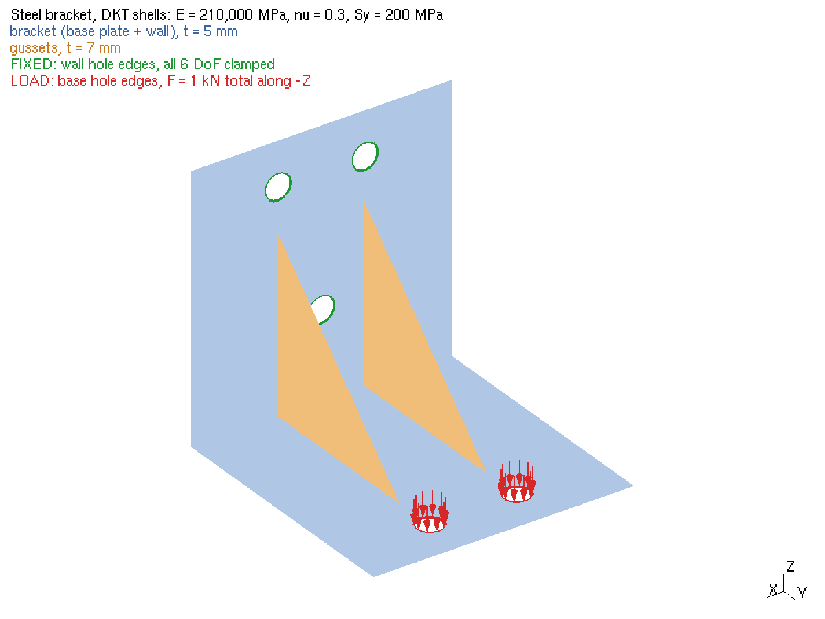
FIGURE 1. Geometry and boundary conditions of the bracket. The edges of the three wall holes are clamped (green), and a total force of $1\,\mathrm{kN}$ along $-z$ is applied on the edges of the two base holes (red). All dimensions are in millimeters.
The material is steel, with an elastic modulus $E = 210\,000\,\mathrm{MPa}$, a Poisson ratio $\nu = 0.3$ and an elastic limit $S_y = 200\,\mathrm{MPa}$. It is assumed to be isotropic and homogeneous, meaning that it has the same properties at every point and in all directions.
How does a shell element represent a plate?
A shell element describes a plate by its mid-surface. Each node has six degrees of freedom: three displacements and three rotations. The displacements in the plane of the plate stretch it (membrane behaviour), and the rotations bend it (plate behaviour). In the DKT formulation used here (discrete Kirchhoff, quadrilateral form DKQ [ref. 2]), the normal to the mid-surface stays straight and normal during the deformation, as in the classical thin plate theory, so the transverse shear deformation is neglected. This holds when the plate is thin compared with its span: here the ratio is $5/100$ for the base and the wall.
The element computes, at each point of the mid-surface, the membrane forces $N$ ($\mathrm{N/mm}$) and the bending moments $M$ ($\mathrm{N \cdot mm/mm}$). The stress varies linearly through the thickness $t$, and is largest on the two skins of the plate, at $\pm t/2$:
$$ \begin{equation} \sigma = \frac{N}{t} \pm \frac{6 M}{t^2}. \end{equation} $$
The stresses and strains are therefore extracted on the lower skin (INF, on the side opposite to the normal of the element) and on the upper skin (SUP), and the larger of the two values is retained at each point. On the skins, the stress is plane ($\sigma_{zz} = 0$ in the frame of the plate), and the von Mises stress is
$$ \begin{equation} \sigma_{VM} = \sqrt{\sigma_{xx}^2 + \sigma_{yy}^2 - \sigma_{xx}\sigma_{yy} + 3\tau_{xy}^2}. \end{equation} $$
The stress components $\sigma_{xx}$, $\sigma_{yy}$ and $\tau_{xy}$ are given in the local frame of each plate: $x$ along $X$ and $y$ along $Y$ in the base, $x$ along $X$ and $y$ along $Z$ in the wall, $x$ along $Y$ and $y$ along $Z$ in the gussets. The normals of the elements point to $+z$ in the base, $+y$ in the wall and $+x$ in the gussets, so each skin is the same physical face over a whole plate.
The stress check uses the inverse reserve factor, the ratio of the von Mises stress to the elastic limit:
$$ \begin{equation} \text{IRF} = \frac{\sigma_{VM}}{S_y}. \end{equation} $$
The part stays elastic where $\text{IRF} < 1$; the margin on the elastic limit is $1 - \text{IRF}$.
Mesh. The geometry was discretised with a structured mesh of 3300 four-node quadrilaterals (QUAD4), with 3466 nodes, generated with Gmsh, plus 200 SEG2 edge elements carrying the boundary conditions and the load. The base and the wall form a single unfolded grid of $16.7 \times 16.7\,\mathrm{mm}$ cells, each split into $5 \times 5$ elements of $3.3\,\mathrm{mm}$. Each hole sits in a block of $2 \times 2$ cells meshed as an O-grid: 40 elements around the circumference, $0.79\,\mathrm{mm}$ long at the hole edge, growing away from it in 7 rings with a ratio of $1.2$. Each gusset is split into three quadrilateral patches through its centroid, with $10 \times 10$ elements each. The base and the gussets share their nodes along the lines where they meet, as do the wall and the gussets, so the plates are rigidly connected. In the base and the wall (2700 elements), the edge aspect ratio is 1.21 on average (1.84 at most), and the skew, measured as the largest deviation of an interior angle from $90^\circ$, is $12^\circ$ on average. In the gussets (600 elements), the elements are more distorted by the triangular shape, with an aspect ratio of 1.53 on average (3.0 at most) and a skew of $26^\circ$ on average, but the stress there is low.
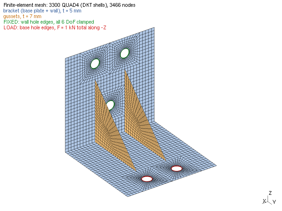
FIGURE 2. Finite element mesh, 3300 QUAD4 elements (DKT shells) and 3466 nodes, refined around the five holes.
Junctions. The plates are modelled at their mid-surfaces, so the thicknesses overlap slightly where they meet: half the thickness of the wall and the base along the corner, and half the thickness of the gussets along their edges. The overlap adds a little stiffness and mass along the junctions; it is small compared with the size of the plates, and it does change the stresses much at the bolt holes of the wall, where the peak is found, more than $25\,\mathrm{mm}$ away from the junctions.
RESULTS
The reaction on the clamped hole edges is $R_z = 1000.0\,\mathrm{N}$, equal and opposite to the applied load, and the horizontal reactions are below $10^{-9}\,\mathrm{N}$, so the model is in equilibrium.
Figure 3 shows the magnitude of the displacement on the deformed shape, magnified 100 times. The wall barely moves, held by its three bolts, and the base bends down as a cantilever from the corner: the displacement grows from the corner to the free edge of the base, where it reaches its maximum, $u_z = -0.139\,\mathrm{mm}$, at mid-width $(50, 100, 0)\,\mathrm{mm}$.
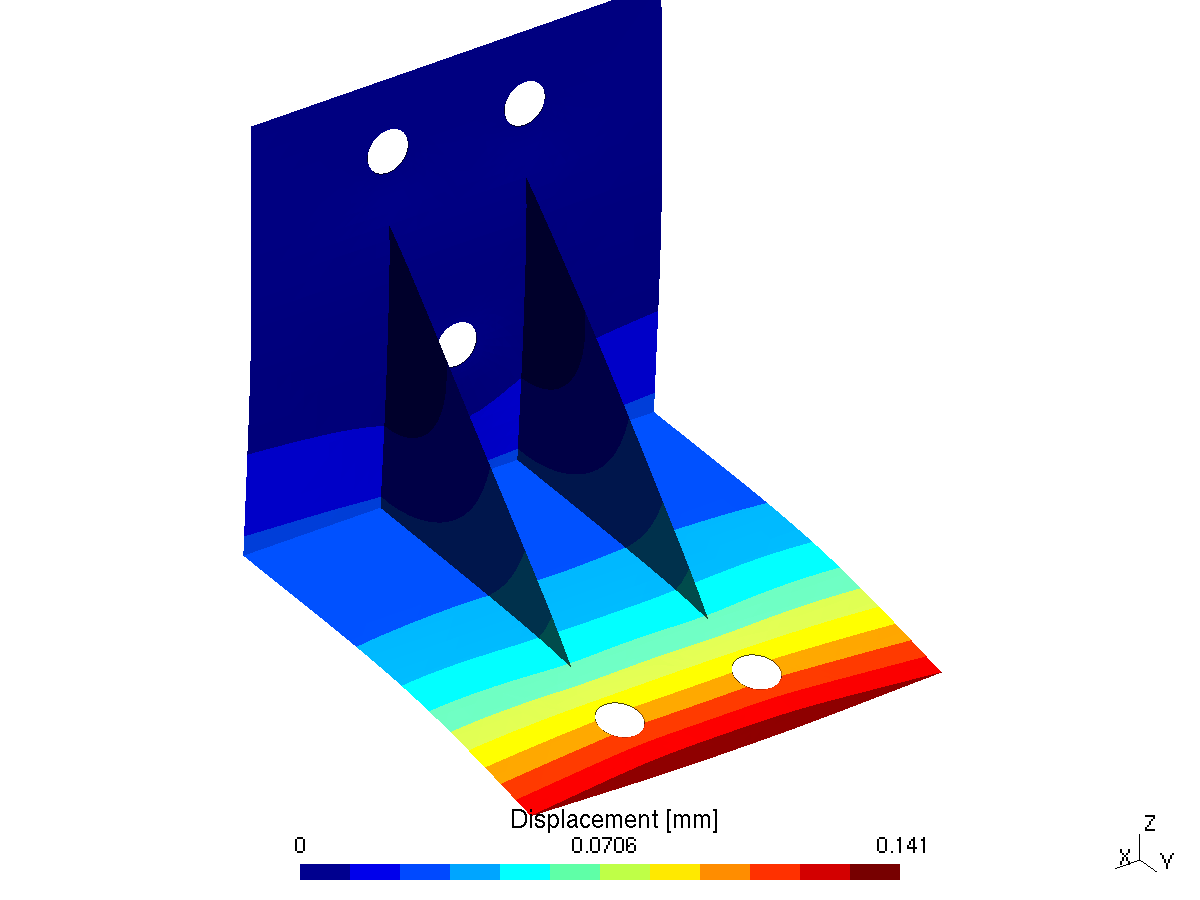
FIGURE 3. Displacement magnitude ($\mathrm{mm}$) on the deformed shape, magnified 100 times. The maximum is at the free edge of the base.
Figure 4 shows the von Mises stress, the larger of the two skins at each point. The load goes from the base holes through the base and the gussets to the wall, and from the wall to the bolts. The stress is highest at the edges of the bolt holes of the wall, where the wall is clamped. The peak is at the lower edge of the lowest hole, at $(50.8, 0, 28.4)\,\mathrm{mm}$: $\sigma_{VM} = 185.3\,\mathrm{MPa}$ on the element values, and $184.1\,\mathrm{MPa}$ after averaging at the nodes. At the two upper bolt holes, the peak is $127.6\,\mathrm{MPa}$, also at their lower edges. Elsewhere, the stress stays below $84\,\mathrm{MPa}$: $84\,\mathrm{MPa}$ at the toes of the gussets on the base, $62\,\mathrm{MPa}$ at their upper ends on the wall, $75\,\mathrm{MPa}$ at most inside the gussets, and $26\,\mathrm{MPa}$ at the loaded holes of the base.
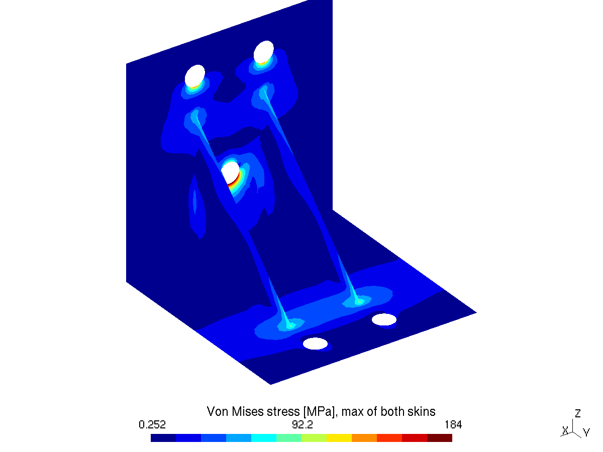
FIGURE 4. Von Mises stress ($\mathrm{MPa}$), larger of the two skins. The peak is at the lower edge of the lowest bolt hole of the wall.
The stress at the peak is a bending stress. In the local frame of the wall, the vertical stress $\sigma_{yy}$ at the lower edge of the lowest hole is $-207\,\mathrm{MPa}$ on the lower skin and $+193\,\mathrm{MPa}$ on the upper skin (figures 5a and 5b). The two skins have opposite signs and nearly the same magnitude, so, from equation $(1)$, the membrane stress $N/t$ is only about $-7\,\mathrm{MPa}$, and the bending stress $6M/t^2$ is about $200\,\mathrm{MPa}$. The wall bends around the clamped edge of the hole, and the hole nearest to the base, between the gussets, takes the largest share of this bending.
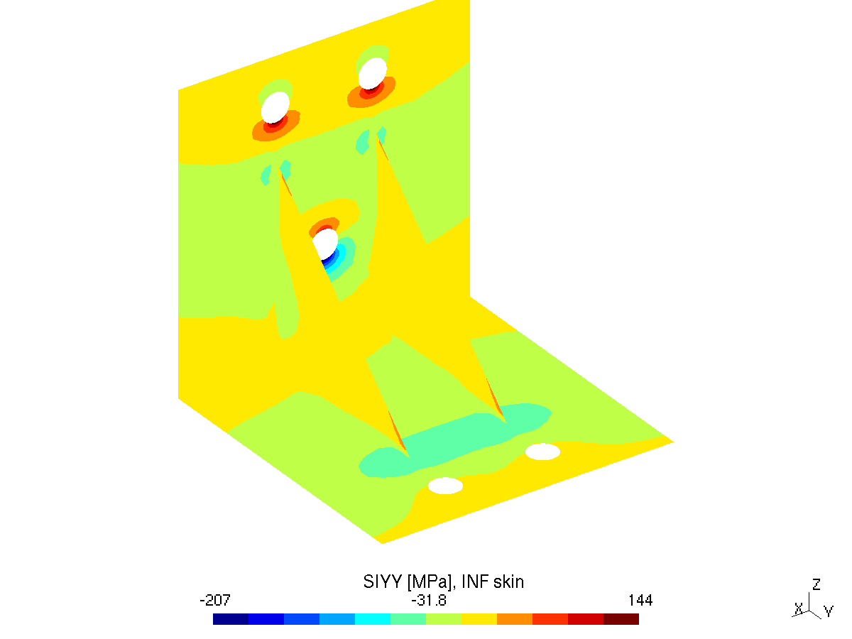
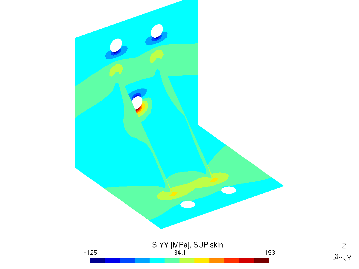
FIGURE 5. Stress $\sigma_{yy}$ ($\mathrm{MPa}$) in the local frame of each plate (vertical in the wall): (a) lower skin, (b) upper skin. At the lower edge of the lowest bolt hole, the two skins have opposite signs: the wall bends.
The equivalent von Mises strain follows the stress (figure 6). It is largest at the same point, $6.7 \times 10^{-4}$, and below $3 \times 10^{-4}$ away from the bolt holes. The strains are small, which confirms the small strain hypothesis.
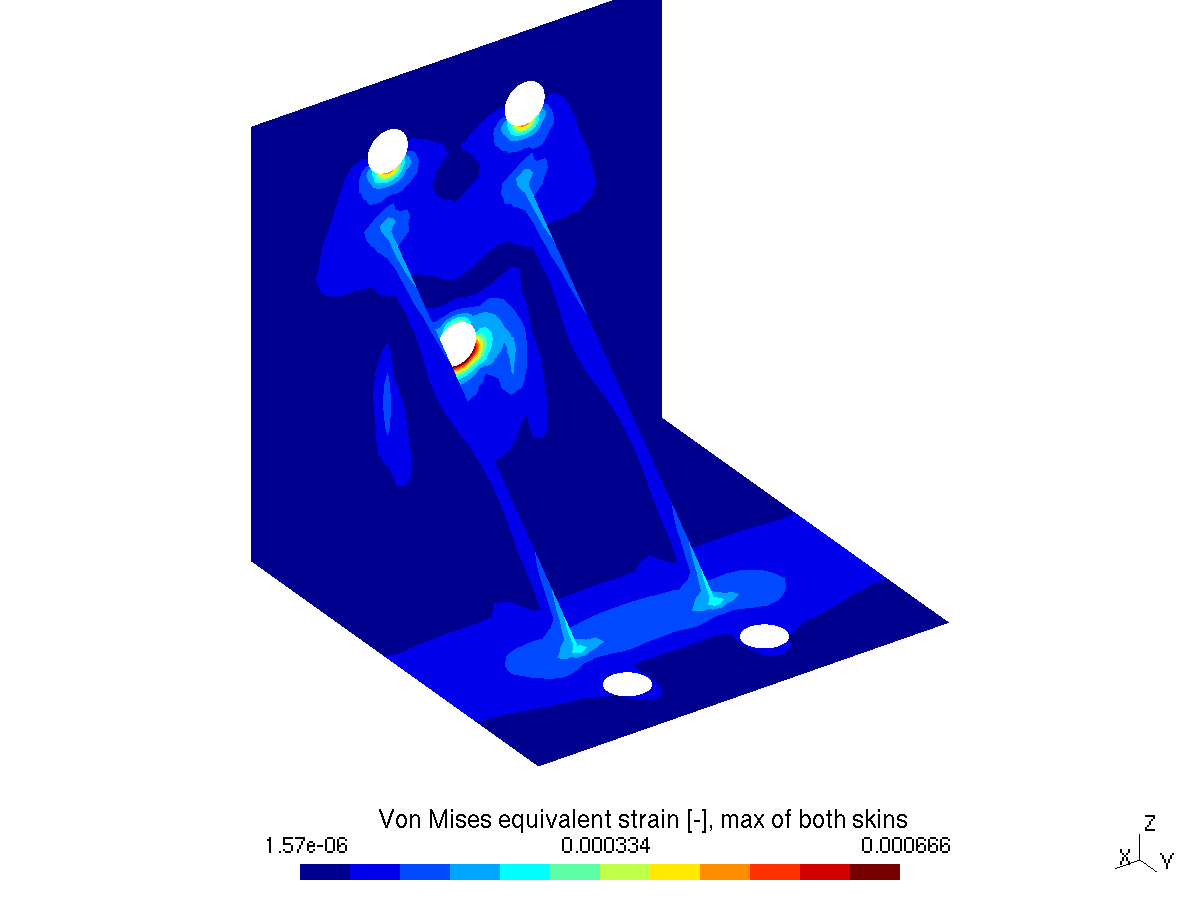
FIGURE 6. Von Mises equivalent strain (-), larger of the two skins.
Figure 7 shows the inverse reserve factor on a fixed scale from 0 to 1, so a red zone would mark the elastic limit. The largest value is $\text{IRF} = 185.3 / 200 = 0.93$, at the lowest bolt hole: the bracket stays elastic, with a margin of $7\%$. At the two upper bolt holes, $\text{IRF} = 0.64$, and everywhere else $\text{IRF} < 0.42$.
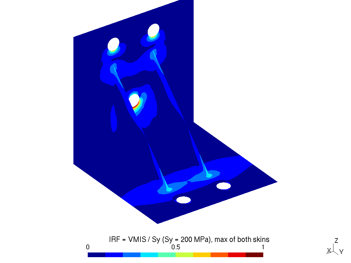
FIGURE 7. Inverse reserve factor $\text{IRF} = \sigma_{VM}/S_y$, larger of the two skins, on a scale from 0 to 1. The maximum is $0.93$ at the lowest bolt hole of the wall.
| Quantity | Value | Location |
|---|---|---|
| Reaction $R_z$ ($\mathrm{N}$) | $1000.0$ | wall holes |
| Displacement $u_z$ ($\mathrm{mm}$) | $-0.139$ | free edge of the base, $(50, 100, 0)$ |
| von Mises, element values ($\mathrm{MPa}$) | $185.3$ | lowest wall hole, lower edge |
| von Mises, nodal values ($\mathrm{MPa}$) | $184.1$ | lowest wall hole, lower edge |
| von Mises, upper wall holes ($\mathrm{MPa}$) | $127.6$ | lower edges |
| von Mises, gusset toes on the base ($\mathrm{MPa}$) | $84$ | $(33.3, 66.7, 0)$, $(66.7, 66.7, 0)$ |
| von Mises, loaded base holes ($\mathrm{MPa}$) | $26$ | hole edges |
| Equivalent strain (-) | $6.7 \times 10^{-4}$ | lowest wall hole, lower edge |
| IRF (-) | $0.93$ | lowest wall hole, lower edge |
CONCLUSION
A linear static finite element analysis of a steel angle bracket with two gussets was performed in Code_aster with thin shell elements, with the goal of computing its displacement, strain and stress fields under a $1\,\mathrm{kN}$ service load and checking it against the elastic limit of the steel. The model is in equilibrium. The base deflects $0.139\,\mathrm{mm}$ at its free edge. The stress is highest at the lower edge of the lowest bolt hole of the wall, where the wall bends around its clamped support: $185\,\mathrm{MPa}$ von Mises, an inverse reserve factor of $0.93$. The bracket stays elastic under this load, with a margin of $7\%$ on the elastic limit; away from the bolt holes, it works at less than half of it.
The margin is small, and the peak is at a clamped hole edge, where the model is the most idealised. The bolts are represented as rigid clamps along the whole hole edge, and the stress there depends on the mesh. The support itself is not modelled: the lower edge of the wall moves $0.02\,\mathrm{mm}$ towards it, where a real support face would push back and change how the bolts share the load. Before the margin is relied on, a mesh refinement around the bolt holes, a model of the bolt heads and of the contact with the support, and a load factor for service overloads would refine the result. Since the analysis is linear, all the results scale with the load: the bracket reaches the elastic limit at the lowest hole for a load of about $1.08\,\mathrm{kN}$. Moving the lowest bolt hole or extending the gussets over it are the obvious design changes to reduce the bending of the wall there.
REFERENCES
- Code_aster, version 17.4.
- J.-L. Batoz, M. Ben Tahar, Evaluation of a new quadrilateral thin plate bending element, International Journal for Numerical Methods in Engineering 18, 1982, pp. 1655-1677.