Stress Concentration & Hole Edge Verification: Plate under Uniaxial Tension
Key result: Code_aster reproduces the stress concentration around a hole in a finite-width steel plate within $1.1\%$ of the reference peak stress ($306.3\,\mathrm{MPa}$ vs $303\,\mathrm{MPa}$, $K = 3.06$), and the compressive stress on the load axis within $4.2\%$ of the Kirsch solution.
SUMMARY
A linear static analysis of a steel plate with a central hole under uniaxial tension was performed as a validation of the finite element analysis (FEA) software Code_aster, following its validation case FORMA01 [ref. 1]. At the hole edge on the load axis, the FEA model gives $\sigma_{yy} = -104.2\,\mathrm{MPa}$ against the analytical $-100\,\mathrm{MPa}$, a difference of $4.2\%$. At the point of maximum stress, the FEA model gives $\sigma_{xx} = 306.3\,\mathrm{MPa}$ against $303\,\mathrm{MPa}$ for the finite-width reference [ref. 2], a difference of $1.1\%$. Both values are within the tolerances of the Code_aster validation case ($15\%$ and $5\%$ respectively), and the stress distributions along both symmetry lines follow the analytical Kirsch solution.
INTRODUCTION
Holes in loaded plates are everywhere in structures: fastener holes, lightening holes, access ports. The hole concentrates the stress at its edge, and the concentration factor drives both static and fatigue sizing.
A plate with a circular hole under axial load is a well-known problem with a closed-form solution, which makes it suitable to compare against finite element methods. Following a rigorous sequence of steps, defining the geometry, the mesh (a discretisation of the geometry), the materials and the boundary conditions, the model should recover a maximum stress about three times the applied load. The objective is to recover that result, and the compressive stress on the load axis, within the tolerances of the Code_aster validation case: $5\%$ on the maximum stress and $15\%$ on the compressive stress.
METHODOLOGY
A rectangular plate with a center hole is modeled in 2D using plane stress elements. The mechanical behavior is assumed to be linear and elastic respecting the small strain hypothesis.
Figure 1 represents the general setup of the problem. The plate dimensions are $400\,\mathrm{mm}$ by $200\,\mathrm{mm}$, with a hole at the center of $20\,\mathrm{mm}$ in diameter. Since the geometry has two symmetric planes, only one quarter is modeled. It is defined by 5 points. Let $O = (0,0)$, $A = (a,0)$, and $B = (0,a)$ with $a = 10$. An arc is drawn from AOB. Let $G = (L,0)$, $F = (L,H)$, and $D = (0,H)$; with $L = 200$ and $H = 100$.
The boundary conditions are the following. The line AG is the symmetric plane, so it is blocked along $Oy$. The line BD is also a symmetric plane, so it is blocked along $Ox$. A tensile pressure of $100\,\mathrm{MPa}$ is applied at GF along $Ox$.
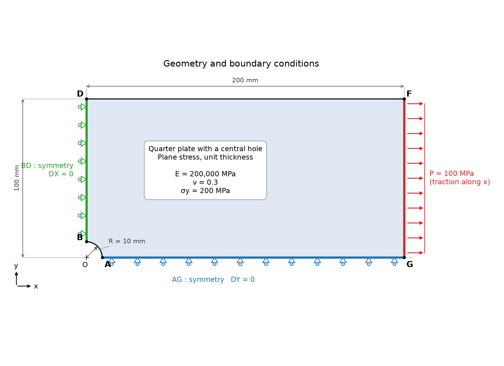
FIGURE 1. Geometric model and boundary conditions of the quarter-plate with a central hole under plane stress. Symmetry conditions are applied along edges $BD$ ($u_x = 0$) and $AG$ ($u_y = 0$). Tensile traction of $P = 100\,\mathrm{MPa}$ is applied along edge $FG$. Material properties: $E = 200\,\mathrm{GPa}$, $\nu = 0.3$, and $\sigma_y = 200\,\mathrm{MPa}$. All dimensions are in millimeters.
The material is steel, with an elastic modulus $E = 200\,000\,\mathrm{MPa}$, a Poisson ratio $\nu = 0.3$, and an elastic strength limit $\sigma_{e} = 200\,\mathrm{MPa}$. The material is assumed to be isotropic and homogeneous, meaning that it has the same properties at every point and in all directions.
What is the stress concentration factor for a plate with a circular hole?
From the equation of motion
$$ \begin{equation} \sigma_{ij,j} + f_i = \rho \ddot{u}_i \quad , \quad i = x,y \end{equation} $$
with summation over the repeated index $j$. We assume a static problem without body forces, $f_i=0$, and $\ddot{u}_i=0$, therefore equation $(1)$ becomes
$$ \begin{equation} \sigma_{ij,j} = 0. \end{equation} $$
By introducing the Airy stress function $\phi$,
$$ \begin{equation} \sigma_{xx} = \frac{\partial^2 \phi}{\partial y^2} \quad , \quad \sigma_{yy} = \frac{\partial^2 \phi}{\partial x^2} \quad , \quad \tau_{xy} = \tau_{yx} = -\frac{\partial^2 \phi}{\partial x \partial y}. \end{equation} $$
The compatibility condition requires (biharmonic equation)
$$ \begin{equation} \nabla^4 \phi = 0 \end{equation} $$
Because the hole is circular, polar coordinates $(r, \theta)$ are used. In these coordinates,
$$ \begin{equation} \sigma_{rr} = \frac{1}{r} \frac{\partial \phi}{\partial r} + \frac{1}{r^2} \frac{\partial ^2 \phi}{\partial \theta^2} \quad, \quad \sigma_{\theta \theta} = \frac{\partial^2 \phi}{\partial r^2} \quad, \quad \tau_{r\theta} = -\frac{\partial}{\partial r} \left( \frac{1}{r} \frac{\partial \phi}{\partial \theta} \right). \end{equation} $$
For $r \geq a$, the Airy stress function $\phi$ that satisfies the biharmonic equation, the far-field loading $\sigma_{xx} \to P$, and the traction-free condition at $r = a$ is
$$ \begin{equation} \phi = \frac{P}{4} \left[ r^2 (1-\cos 2\theta) - 2a^2 \ln r + 2 a^2 \cos 2 \theta - \frac{a^4}{r^2} \cos 2\theta \right] \end{equation} $$
Substituting $(6)$ into $(5)$ gives
$$ \begin{equation} \begin{aligned} \sigma_{rr} &= \frac{P}{2} \left[ 1 - \frac{a^2}{r^2} + \left( 1 - \frac{4a^2}{r^2} + \frac{3a^4}{r^4} \right) \cos 2\theta \right] \\ \sigma_{\theta\theta} &= \frac{P}{2} \left[ 1 + \frac{a^2}{r^2} - \left( 1 + \frac{3a^4}{r^4} \right) \cos 2\theta \right] \\ \tau_{r \theta} &= -\frac{P}{2} \left( 1 + \frac{2a^2}{r^2} - \frac{3a^4}{r^4} \right) \sin 2\theta \end{aligned} \end{equation} $$
At the hole boundary $r = a$, there is neither radial nor shear stress, so
$$ \begin{equation} \sigma_{rr}(a,\theta) = 0 \quad , \quad \tau_{r\theta}(a,\theta) = 0 \end{equation} $$
However, the circumferential stress at the hole boundary is
$$ \begin{equation} \sigma_{\theta \theta} = P (1 - 2 \cos 2\theta) \end{equation} $$
Therefore, the maximum stress occurs at $\theta = \pi/2$.
$$ \begin{equation} \sigma_{\theta \theta}(a,\frac{\pi}{2}) = P (1 - 2 \cos \pi) = 3P \end{equation} $$
Thus, the stress concentration factor $K_{\sigma}= \frac{\sigma_{\text{max}}}{P} = 3$.
Additionally, the stress at $\theta = 0$ is
$$ \begin{equation} \sigma_{\theta \theta}(a,0) = P (1 - 2) = -P \end{equation} $$
Mesh. The geometry was discretized with 8557 linear quadrilateral elements (QUAD4, Code_aster element MECPQU4: bilinear, full 2×2 Gauss integration) and 8777 nodes, plus 277 SEG2 edge elements carrying the boundary conditions and the load. Around the hole the mesh is radial and graded, with the smallest elements at the hole edge where the stress gradient is steepest; away from the hole it becomes a regular coarser grid. The mesh quality is good. The edge aspect ratio is close to 1 everywhere (mean 1.03, maximum 1.19), and the corner Jacobian ratio is at least 0.96 (mean 0.99), so no element is folded or badly tapered. The skew, measured as the largest deviation of an interior angle from $90^\circ$, averages $4^\circ$ and is below $10^\circ$ in $84\%$ of the elements. The most distorted elements (maximum $44^\circ$, 24 elements above $40^\circ$) lie in the outer blocks, more than $40\,\mathrm{mm}$ from the hole centre, where the grid fans out from the $45^\circ$ line. There the stress field is nearly uniform, so they do not affect the results. The elements at the hole edge, where the stress concentration is evaluated, are almost perfect squares, as shown in figure 2.
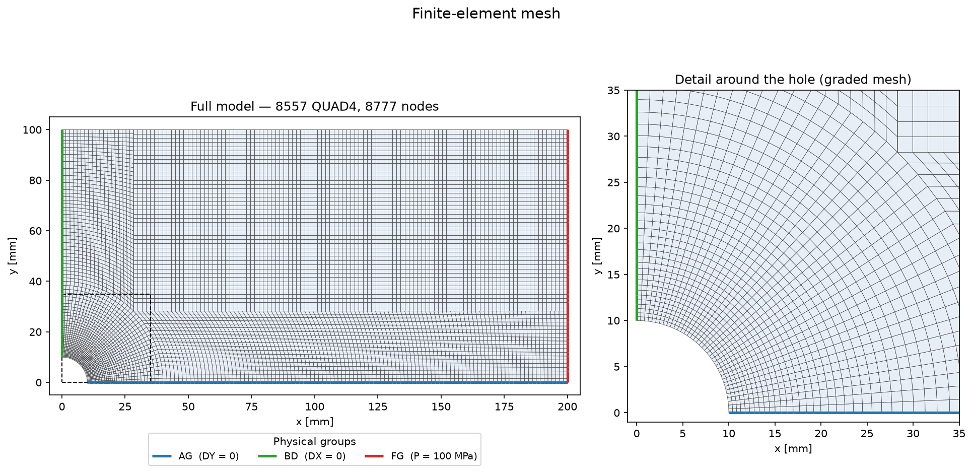
FIGURE 2. Finite element mesh, full model and detail around the hole.
Analytical reference. For an infinite plate under a remote stress $P$ along $x$, the hoop stress on the hole edge ($r = a$) is (Kirsch):
$$\sigma_{\theta\theta}(a, \theta) = P\,(1 - 2\cos 2\theta)$$
with $\theta$ measured from the load axis. It gives $\sigma_{xx} = 3P = 300\,\mathrm{MPa}$ at $B = (0, a)$, on the edge transverse to the load, and $\sigma_{yy} = -P = -100\,\mathrm{MPa}$ at $A = (a, 0)$, on the load axis. Because the plate is finite, its width raises the concentration factor slightly: Peterson's charts give $\sigma_{xx} \approx 303\,\mathrm{MPa}$ at $B$ [ref. 2], which is the reference used by the Code_aster validation case.
RESULTS
The reaction on the symmetry edge $BD$ is $-10\,000\,\mathrm{N}$, equal to the applied load ($100\,\mathrm{MPa} \times 100\,\mathrm{mm}$, unit thickness), so the model is in equilibrium.
Figure 3 shows the magnitude of the displacement across the plate. Away from the hole the contours are nearly straight and evenly spaced, as for a uniform elongation along $x$; they bend only near the hole, where the material around the opening deforms more. The displacement grows from zero on the symmetry edge $BD$ to its maximum on the loaded edge $FG$: $u_x = 0.1013\,\mathrm{mm}$ at $G$, and $\bar{u}_x = 0.1012\,\mathrm{mm}$ on average along $FG$. The average is the displacement that measures the compliance, because the traction on $FG$ is uniform. Without the hole, the same plate would elongate by $u_x = PL/E = 100 \times 200 / 200\,000 = 0.1\,\mathrm{mm}$, so the hole increases the compliance of the plate by $1.2\%$. This agrees with the dilute estimate for a circular hole in plane stress, $E/E_{\text{eff}} = 1 + 3f$ [ref. 3], where $f = \pi a^2 / (4LH) = 0.39\%$ is the area fraction of the hole, which gives $1.18\%$.
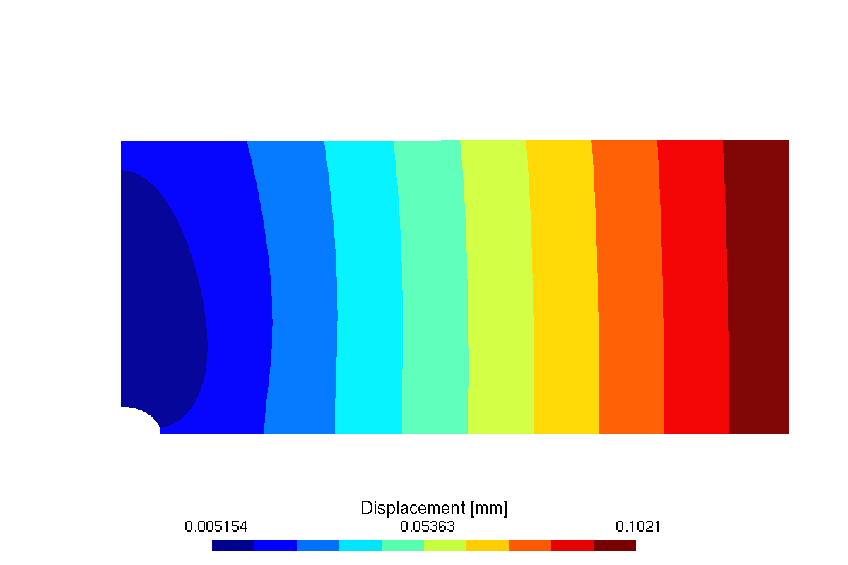
FIGURE 3. Displacement magnitude ($\mathrm{mm}$). The maximum is on the loaded edge $FG$.
Figure 4 shows the equivalent von Mises stress distribution across the plate. The stress concentrates near the hole boundary. The maximum von Mises stress is $\sigma_{VM} = 301.1\,\mathrm{MPa}$, at $B$, which is higher than the elastic limit $\sigma_e = 200\,\mathrm{MPa}$. The zone where the yield stress is exceeded (Figure 5) is small, but a model of the real behaviour of the plate at this load level would have to include plastic, nonlinear material behaviour there.
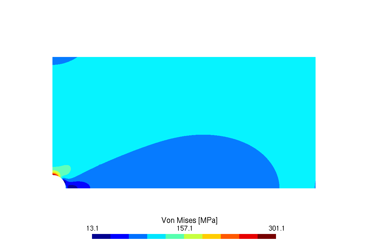
FIGURE 4. Equivalent von Mises stress ($\mathrm{MPa}$). The maximum, $301.1\,\mathrm{MPa}$, is at the hole edge at $B$.
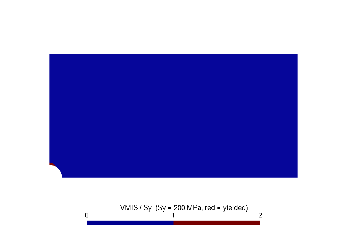
FIGURE 5. Von Mises stress divided by the yield stress ($\sigma_e = 200\,\mathrm{MPa}$). The small zone at the hole edge in red exceeds yield.
Figure 6 shows the stresses along $x$ and $y$, and the shear stress $\sigma_{xy}$. In Figure 6a, the maximum is at $B = (a, \theta = \pi/2)$: $\tilde{\sigma}_{xx} = 306.3\,\mathrm{MPa}$, a relative error of $1.1\%$ against the reference value $\sigma_{xx} = 303\,\mathrm{MPa}$. In Figure 6b, the minimum is at $A = (a, \theta = 0)$: $\tilde{\sigma}_{yy} = -104.2\,\mathrm{MPa}$, meaning that this area is in compression, a relative error of $4.2\%$ against the reference value $\sigma_{yy} = -100\,\mathrm{MPa}$. Figure 6c shows the shear stress, which is largest in magnitude ($-83.1\,\mathrm{MPa}$) at the hole edge at $\theta \approx 64^\circ$, close to the $63.2^\circ$ predicted by the Kirsch solution.
| Point | Quantity | FEA | Reference | Difference | Tolerance |
|---|---|---|---|---|---|
| $B = (0, 10)$ | $\sigma_{xx}$ ($\mathrm{MPa}$) | $306.3$ | $303$ | $+1.1\%$ | $5\%$ |
| $A = (10, 0)$ | $\sigma_{yy}$ ($\mathrm{MPa}$) | $-104.2$ | $-100$ | $+4.2\%$ | $15\%$ |
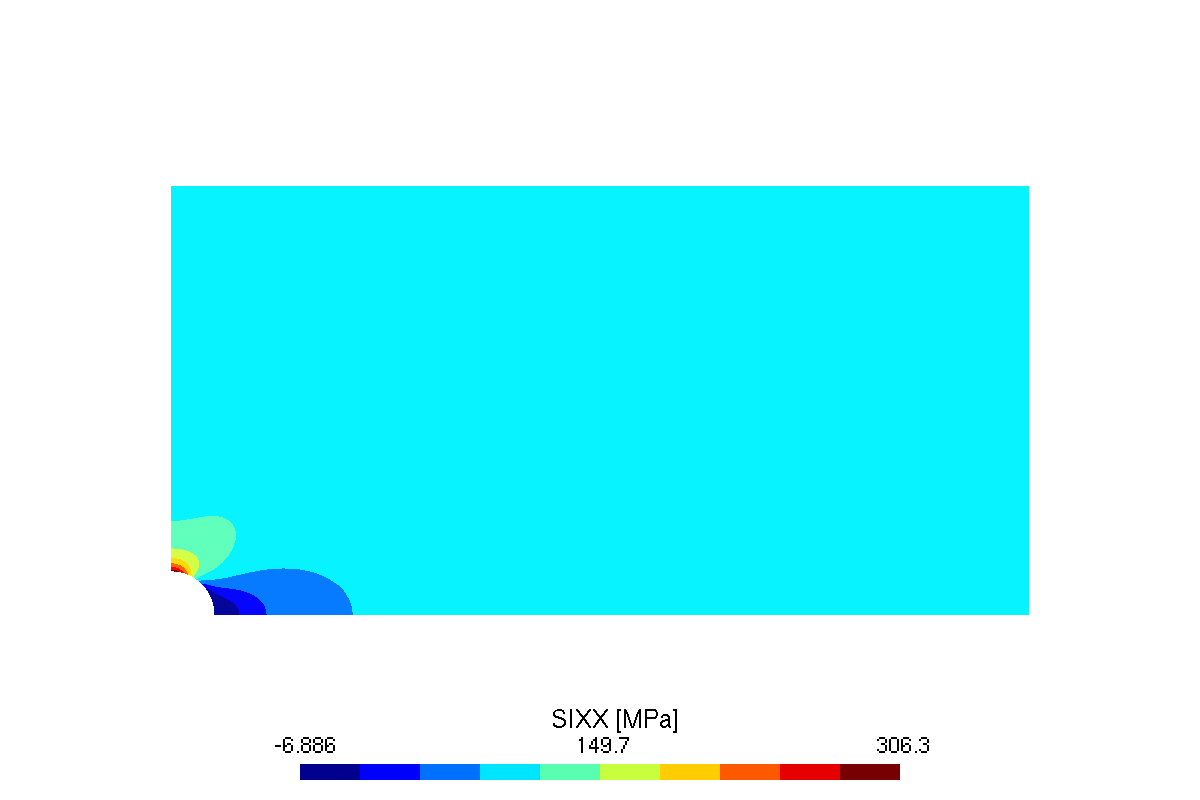
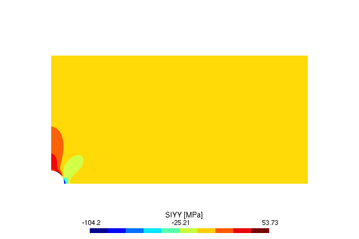
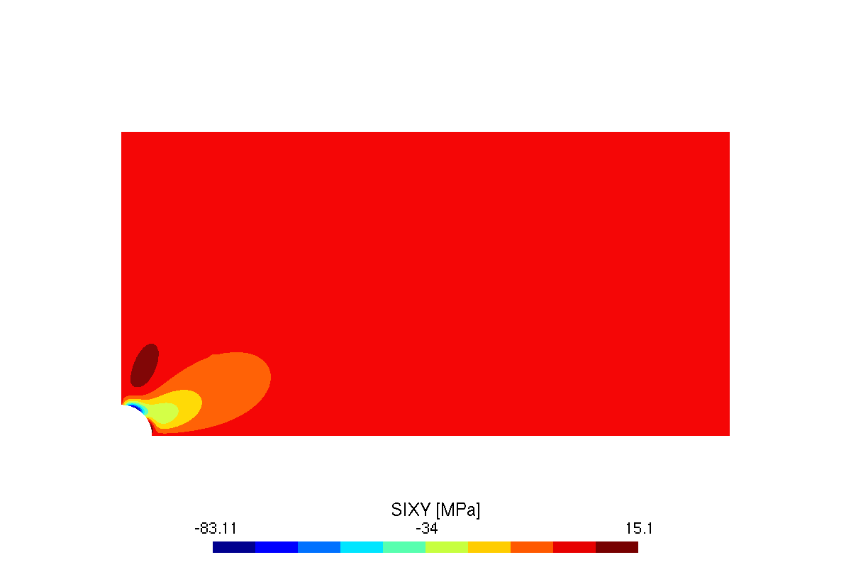
FIGURE 6. Stress components ($\mathrm{MPa}$): (a) $\sigma_{xx}$, maximum at $B$; (b) $\sigma_{yy}$, minimum (compression) at $A$; (c) $\sigma_{xy}$.
Figure 7 shows the stress concentration factor $K = \sigma/P$ along the two symmetry lines: along $BD$ in Figure 7a and along $AG$ in Figure 7b. At $B$, $K = 306.3 / 100 = 3.06$, against 3.00 for an infinite plate and 3.03 for this finite plate. Overall, the FEA results closely follow the closed-form solution for both $\sigma_{xx}$ and $\sigma_{yy}$, along $BD$ and along $AG$.
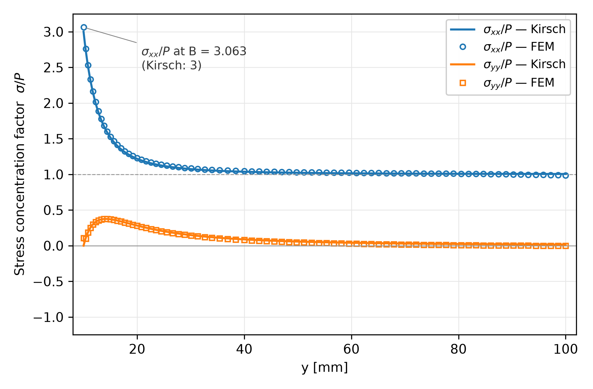
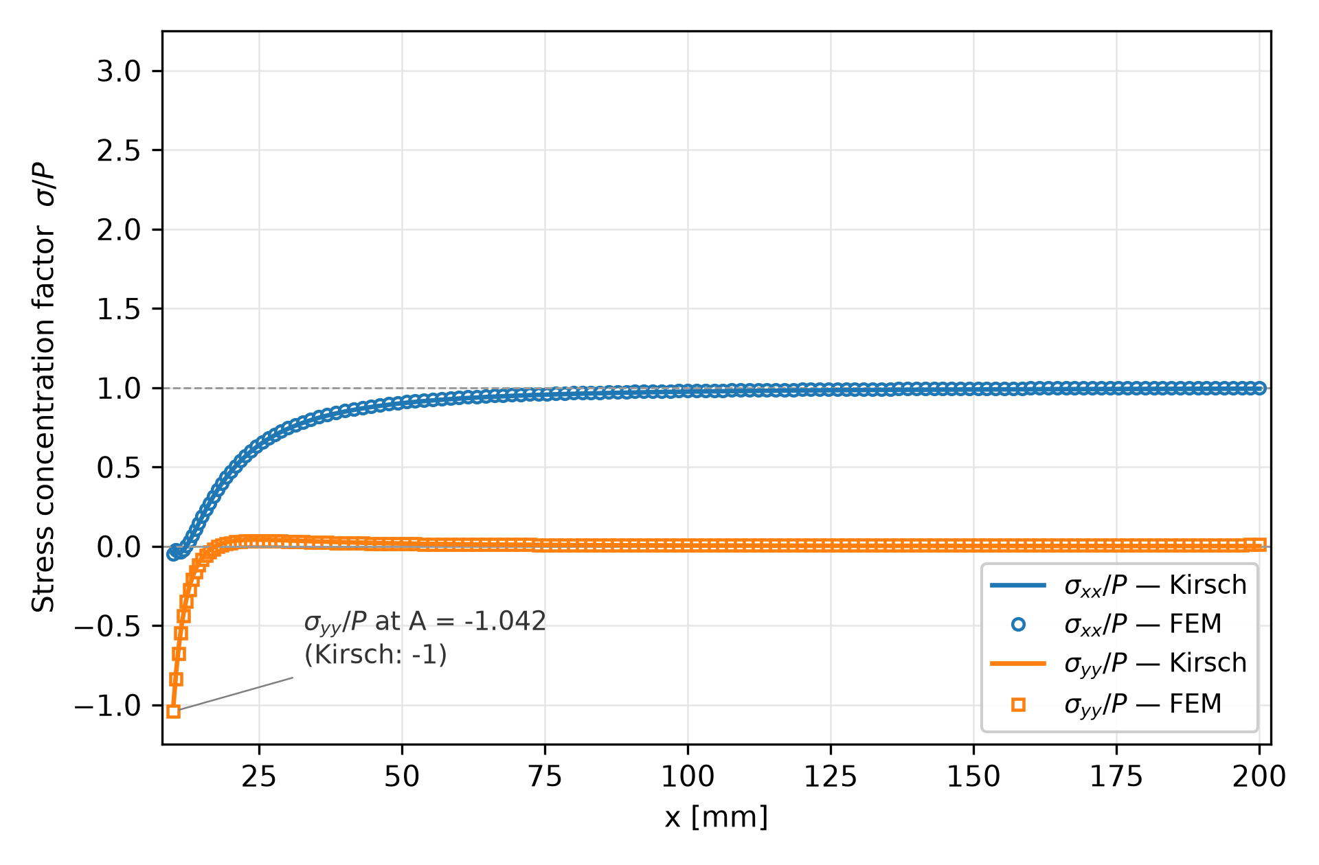
FIGURE 7. Normalised stresses $K = \sigma/P$, FEA against Kirsch. (a) Along the symmetry line $BD$ ($x = 0$), from the hole edge to the free edge: the stress decays from 3.06 at $B$ to the nominal value within about two hole diameters. (b) Along the symmetry line $AG$ ($y = 0$), from the hole edge to the loaded edge: the compressive $\sigma_{yy}$ is limited to a small zone near $A$.
CONCLUSION
A two-dimensional linear static finite element analysis of a plate with a central hole under axial tension was performed in Code_aster, with the goal of predicting a stress concentration close to the analytical solution. Code_aster reproduces it: the maximum stress is within $1.1\%$ of the finite-width reference and the compressive stress on the load axis within $4.2\%$ of the analytical value, both inside the validation tolerances, and the stress profiles along both symmetry lines agree with the Kirsch solution. The larger difference at $A$ is expected, because there the reference value is small and the stress changes sign within a few millimetres of the edge; the stress there is extrapolated from Gauss points to the node on a linear mesh.
With $P = 100\,\mathrm{MPa}$, the peak stress exceeds the $200\,\mathrm{MPa}$ yield stress in a small zone at the hole edge. This linear analysis is valid as a verification of the elastic stress concentration; predicting the actual behaviour of the plate at this load level would require an elastoplastic analysis, and the same workflow extends to it directly.
REFERENCES
- Code_aster validation case FORMA01
- R. E. Peterson, Stress Concentration Factors, J. Wiley, p. 150.
- M. Kachanov, I. Tsukrov, B. Shafiro, Effective moduli of solids with cavities of various shapes, Applied Mechanics Reviews 47(1S), 1994, pp. S151-S174.