
Sandwich Beam in 4-Point Flexure: 3D FEA vs Sandwich Beam Theory
Key result: under $P = 1\,\mathrm{kN}$, the carbon/epoxy and foam sandwich beam deflects $1.87\,\mathrm{mm}$ at the load points, $3.2\%$ below sandwich beam theory, and $85\%$ of that deflection comes from the shear of the foam core. The shear force and bending moment diagrams computed from the 3D stresses match statics exactly. The face stress ($86.0\,\mathrm{MPa}$) and the core shear stress ($1.469\,\mathrm{MPa}$) are within $0.4\%$ of theory.
SUMMARY
A sandwich beam with unidirectional carbon/epoxy faces and a foam core, loaded in 4-point flexure, was analysed in the finite element analysis (FEA) software Code_aster [ref. 1] with a 3D model: 26112 twenty-node hexahedra (HEXA20) in a structured mesh, with orthotropic faces and an isotropic core. The shear force and bending moment along the beam were integrated from the stresses at the integration points, and the deflection was split into its bending and shear parts with a second solution in which every shear modulus is multiplied by 100. The results were compared with the sandwich beam theory of Allen [ref. 2].
The shear force ($\pm 500\,\mathrm{N}$ in the shear spans, $0$ between the loads) and the bending moment ($20.80\,\mathrm{N \cdot m}$ between the loads) match statics to four digits. The stresses match the theory: $85.95\,\mathrm{MPa}$ in the faces at mid-span ($85.65\,\mathrm{MPa}$ in theory), and $1.469\,\mathrm{MPa}$ of shear, nearly uniform, in the core ($1.467\,\mathrm{MPa}$). At the load points, the beam deflects $1.873\,\mathrm{mm}$ against $1.934\,\mathrm{mm}$ in theory ($-3.2\%$): $0.283\,\mathrm{mm}$ of bending ($+0.5\%$) and $1.590\,\mathrm{mm}$ of core shear ($-3.8\%$). At mid-span, the deflection is $2.131\,\mathrm{mm}$ against $2.099\,\mathrm{mm}$ ($+1.5\%$). The shear of the soft core makes up $85\%$ of the deflection: a classical (Euler-Bernoulli) beam model would predict $0.28\,\mathrm{mm}$, nearly seven times too little.
INTRODUCTION
A sandwich beam is made of two thin, stiff faces bonded to a thick, light core. The faces carry the bending moment as a tension-compression couple, and the core keeps them apart and carries the shear force. The result is a very high bending stiffness for its weight, which is why sandwich panels are found in aircraft floors, wind turbine blades, boat hulls and racing cars.
The price is a soft core. A foam core has a shear modulus about a thousand times lower than the faces' longitudinal modulus, so the beam deforms in shear much more than a solid beam does. Classical beam theory, which neglects shear deformation, badly underestimates the deflection of sandwich beams. The 4-point flexure test (ASTM D7249 [ref. 3] for the faces, ASTM D7250 [ref. 4] for the flexural and shear stiffnesses) is the standard way to measure these properties: between the two loads, the beam is in pure bending, and in the two outer spans it carries a constant shear force.
This study models the test in 3D and checks the model against sandwich beam theory on three quantities: the shear force and bending moment diagrams, the stresses in the faces and the core, and the deflection at the loading points, split into its bending and shear parts.
METHODOLOGY
The beam is modelled with 3D solid elements. The mechanical behaviour is assumed to be linear and elastic, respecting the small strain hypothesis.
Figure 1 represents the general setup of the problem. The beam ($x$ along its axis, $y$ through its thickness, $z$ across its width) is $2d + s = 203.2\,\mathrm{mm}$ long and $b = 25.4\,\mathrm{mm}$ wide. Its two faces are $t_f = 0.711\,\mathrm{mm}$ thick and the core is $h_c = 12.7\,\mathrm{mm}$ thick, for a total thickness $H = 14.122\,\mathrm{mm}$. The beam rests on two line supports across its width, along the bottom edges at $x = 0$ and $x = 203.2\,\mathrm{mm}$: a pin ($u_x = u_y = 0$) and a roller ($u_y = 0$), with $u_z = 0$ at one node to remove the last rigid-body motion. Two line loads $P/2 = 500\,\mathrm{N}$ along $-y$, spread uniformly over the width ($19.69\,\mathrm{N/mm}$), are applied along the top edges at the loading points $x_1 = d = 41.6\,\mathrm{mm}$ and $x_2 = d + s = 161.6\,\mathrm{mm}$. The two shear spans are $d = 41.6\,\mathrm{mm}$ long, and the moment span between the loads is $s = 120\,\mathrm{mm}$.
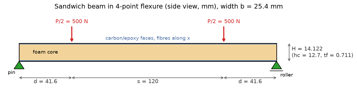
FIGURE 1. Geometry and boundary conditions of the sandwich beam (side view, dimensions in millimeters, thicknesses not to scale with the labels).
The faces are unidirectional carbon/epoxy with the fibres along the beam axis: longitudinal modulus $E_f = 139.4\,\mathrm{GPa}$ and shear modulus $G_f = 3.36\,\mathrm{GPa}$. They are modelled as an orthotropic material in the global frame ($L = x$, $T = y$, $N = z$). Their transverse properties were not given and were set to typical values for this class of material: $E_T = E_N = 10\,\mathrm{GPa}$, $\nu_{LT} = \nu_{LN} = 0.3$, $\nu_{TN} = 0.4$, $G_{TN} = E_T / (2(1 + \nu_{TN})) = 3.57\,\mathrm{GPa}$. They play almost no part in the bending of the beam. The foam core is isotropic, with $E_c = 92\,\mathrm{MPa}$ and $G_c = 35\,\mathrm{MPa}$, hence $\nu_c = E_c / (2 G_c) - 1 = 0.314$.
Sandwich beam theory
In the theory of sandwich beams with thin faces [ref. 2], the faces carry the bending moment and the core carries the shear force. The bending stiffness $D$ and the shear stiffness $S$ of the beam are
$$ \begin{equation} D = \frac{E_f b t_f e^2}{2} + \frac{E_f b t_f^3}{6} + \frac{E_c b h_c^3}{12} = 2.270 \times 10^8\,\mathrm{N \cdot mm^2}, \qquad S = \frac{G_c b e^2}{h_c} = 12\,590\,\mathrm{N}, \end{equation} $$
where $e = h_c + t_f = 13.411\,\mathrm{mm}$ is the distance between the centroids of the faces. The first term of $D$, the faces working as a couple, makes up $99.7\%$ of it. With $F = P/2$, the shear force is $V = F$ in the shear spans and $0$ between the loads, and the bending moment rises linearly to $M = F d = 20.8\,\mathrm{N \cdot m}$ and stays constant between the loads. The deflection is the sum of a bending part and a shear part. At the loading points:
$$ \begin{equation} \delta = \underbrace{\frac{F d^2 (3L - 4d)}{6D}}_{\text{bending}} + \underbrace{\frac{F d}{S}}_{\text{shear}} = 0.282 + 1.652 = 1.934\,\mathrm{mm}, \end{equation} $$
and at mid-span, $$\delta = F d (3L^2 - 4d^2)/(24 D) + F d / S = 0.447 + 1.652 = 2.099\,\mathrm{mm}$$, with $L = 2d + s$. The core shears only in the shear spans, so the shear deflection is the same at the load points and at mid-span. The stresses are $\sigma_{xx} = M/(b t_f e) = 85.9\,\mathrm{MPa}$ in the faces between the loads and $\tau_{xy} = V/(b e) = 1.468\,\mathrm{MPa}$ in the core of the shear spans; the profiles of figure 7 use the exact composite beam formulas, which differ from these by less than $0.3\%$.
From the 3D stresses to V, M and the deflections
Shear force and bending moment. The mesh is structured, so the beam can be cut into slices one element long ($\Delta x \approx 1\,\mathrm{mm}$). Over each slice, the shear force and the bending moment are integrated from the stresses at the integration (Gauss) points, with $w_g$ the volume each point represents:
$$ \begin{equation} V = -\frac{1}{\Delta x} \sum_g w_g\, \sigma_{xy,g}, \qquad M = -\frac{1}{\Delta x} \sum_g w_g\, \sigma_{xx,g} \left(y_g - \frac{H}{2}\right). \end{equation} $$
These are the averages of $V$ and $M$ over the slice, exact when they vary linearly along it. $V$ is positive for an upward force on the left part, and $M$ is positive when the bottom face is in tension.
Deflection. The supports and the loads are lines on the edges of the beam, so the soft core is crushed locally beneath them. Under each support, the mid-plane of the beam moves down by $0.37\,\mathrm{mm}$ over the first few millimeters (dotted line of figure 4). This settlement is not part of the beam's deflection, and a real test fixture measures the deflection relative to the supports. It was removed by fitting the beam solution, $w = c_0 + c_1 x + c_3 x^3$, to the mid-plane deflection of each shear span between $x = 10$ and $30\,\mathrm{mm}$, clear of the local effects at the support and at the load. The constant $c_0 = 0.282\,\mathrm{mm}$ is the settlement on the supports, and the beam deflection is the mid-plane deflection minus $c_0$. The fit window can move by $\pm 2\,\mathrm{mm}$ without changing the deflections by more than $0.3\%$.
Bending and shear parts. A second solution was computed with every shear modulus multiplied by $k = 100$. Its shear deflection is $k$ times smaller and its bending deflection is unchanged, so the two solutions $\delta$ and $\delta_k$ give
$$ \begin{equation} \delta_{\text{bending}} = \frac{k\, \delta_k - \delta}{k - 1}, \qquad \delta_{\text{shear}} = \delta - \delta_{\text{bending}}. \end{equation} $$
(With $k = 1000$, the system of equations becomes too ill-conditioned for the direct solver.)
Mesh. The geometry was discretised with a structured mesh of 26112 twenty-node hexahedra (HEXA20) and 119977 nodes, generated with Gmsh: $204$ elements along the beam ($42$ in each shear span, $120$ between the loads, $0.99$ to $1.0\,\mathrm{mm}$ long), $2$ through each face ($0.36\,\mathrm{mm}$), $12$ through the core ($1.06\,\mathrm{mm}$) and $8$ across the width ($3.2\,\mathrm{mm}$). The faces and the core share their nodes, so they are perfectly bonded. A mesh with half as many divisions in every direction (3264 HEXA20) gives the same deflections within $0.08\%$ and the same stresses within $0.3\%$, so the results do not depend on the mesh.
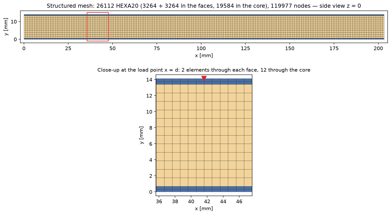
FIGURE 2. Finite element mesh, 26112 HEXA20 elements and 119977 nodes, side view; close-up at the loading point $x = d$.
RESULTS
The reactions on the two supports are $R_y = 500.0\,\mathrm{N}$ each, and the other components are below $10^{-8}\,\mathrm{N}$, so the model is in equilibrium.
Figure 3 shows the displacement on the deformed shape, magnified 5 times. The two shear spans tilt almost as straight lines, the signature of shear deformation, and the moment span between the loads bends into a shallow arc.
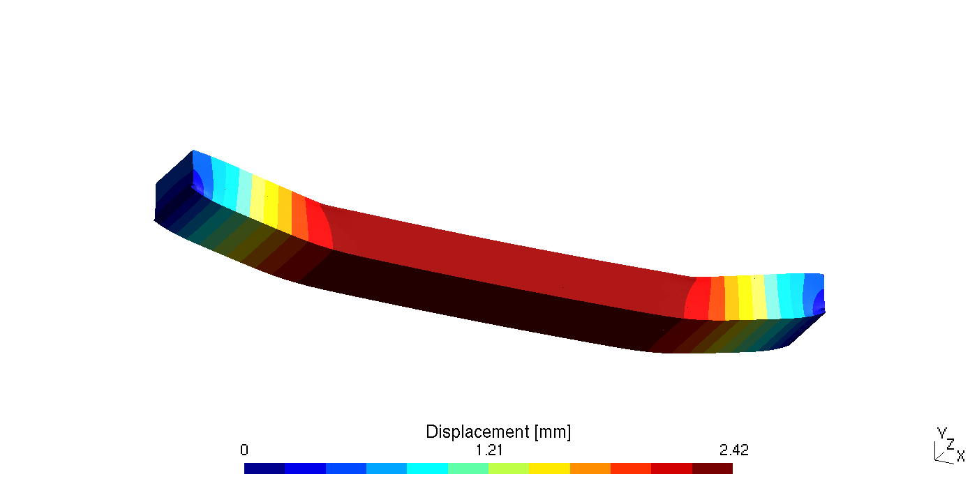
FIGURE 3. Displacement magnitude ($\mathrm{mm}$) on the deformed shape, magnified 5 times.
Deflections due to flexure and shear
Figure 4 compares the deflection along the beam with the theory. Once the settlement on the supports is removed, the FEA follows the theory along the whole beam. The only visible difference is at the loading points, where the theory has a sharp kink and the FEA a rounded one. The beam with stiffened shear moduli (orange) follows the bending-only theory.
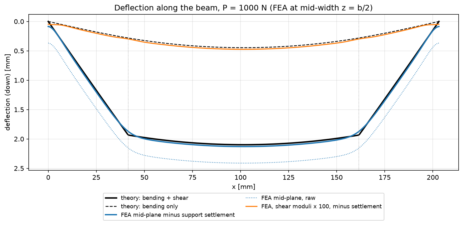
FIGURE 4. Deflection along the beam ($\mathrm{mm}$, downwards), FEA at mid-width against sandwich beam theory. Solid blue: mid-plane minus the settlement on the supports. Dotted: raw mid-plane. Orange: shear moduli multiplied by 100.
| Deflection ($\mathrm{mm}$) | FEA | Theory | Difference |
|---|---|---|---|
| Load points $x_1, x_2$: bending | $0.283$ | $0.282$ | $+0.5\%$ |
| Load points $x_1, x_2$: shear | $1.590$ | $1.652$ | $-3.8\%$ |
| Load points $x_1, x_2$: total | $\mathbf{1.873}$ | $\mathbf{1.934}$ | $\mathbf{-3.2\%}$ |
| Mid-span: bending | $0.458$ | $0.447$ | $+2.6\%$ |
| Mid-span: shear | $1.672$ | $1.652$ | $+1.2\%$ |
| Mid-span: total | $2.131$ | $2.099$ | $+1.5\%$ |
The bending part at the loading points is within $0.5\%$ of the theory. The shear part, $85\%$ of the total, is $3.8\%$ lower. Two effects of the 3D model explain the gaps, and both lie outside the thin-face theory:
- The rounded kink at the load points. In the theory, the core shear strain drops from $F/S$ to zero exactly at the load, so the slope of the beam jumps there. In the 3D model, the faces have their own bending stiffness, $E_f b t_f^3/12$ each, and the core deforms under the line load. The shear strain fades out over a few millimeters on both sides of the load instead, and the faces bend locally to follow it. The corner of the deflection curve is rounded, so its tip, the load point, sits lower than the sharp corner of the theory (figure 4). The length over which this happens is about $\sqrt{E_f b t_f^3/(6S)} = 4\,\mathrm{mm}$, and the rounding takes off about $F/S \times 4\,\mathrm{mm}/2 \approx 0.08\,\mathrm{mm}$: this is the $0.06\,\mathrm{mm}$ missing from the shear part at the load points.
- The same effect seen from mid-span. The shear strain that fades into the moment span adds a little deflection beyond the load points, so at mid-span the shear part is $1.2\%$ higher than in the theory, not lower.
The bending part at mid-span, $+2.6\%$, includes the same local effects, seen through the stiffened solution. The deflection on the faces differs from that of the mid-plane only near the loads and supports, where the core is crushed (top face $0.08\,\mathrm{mm}$ lower than the mid-plane under the loads).
Shear force and bending moment diagrams
Figures 5 and 6 show the shear force and bending moment integrated from the stresses, one point per slice of elements, against the diagrams of statics. The shear force is $500.00\,\mathrm{N}$ in the shear spans, below $0.001\,\mathrm{N}$ between the loads, and the bending moment is $20.800\,\mathrm{N \cdot m}$ between the loads. The largest difference with statics, anywhere along the beam, is below $0.01\%$ of the peak moment. This is expected from a model in equilibrium. It also checks the stress integration, which is used next to separate the share of each layer.
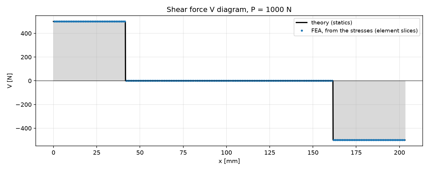
FIGURE 5. Shear force diagram ($\mathrm{N}$), FEA (points) against statics.
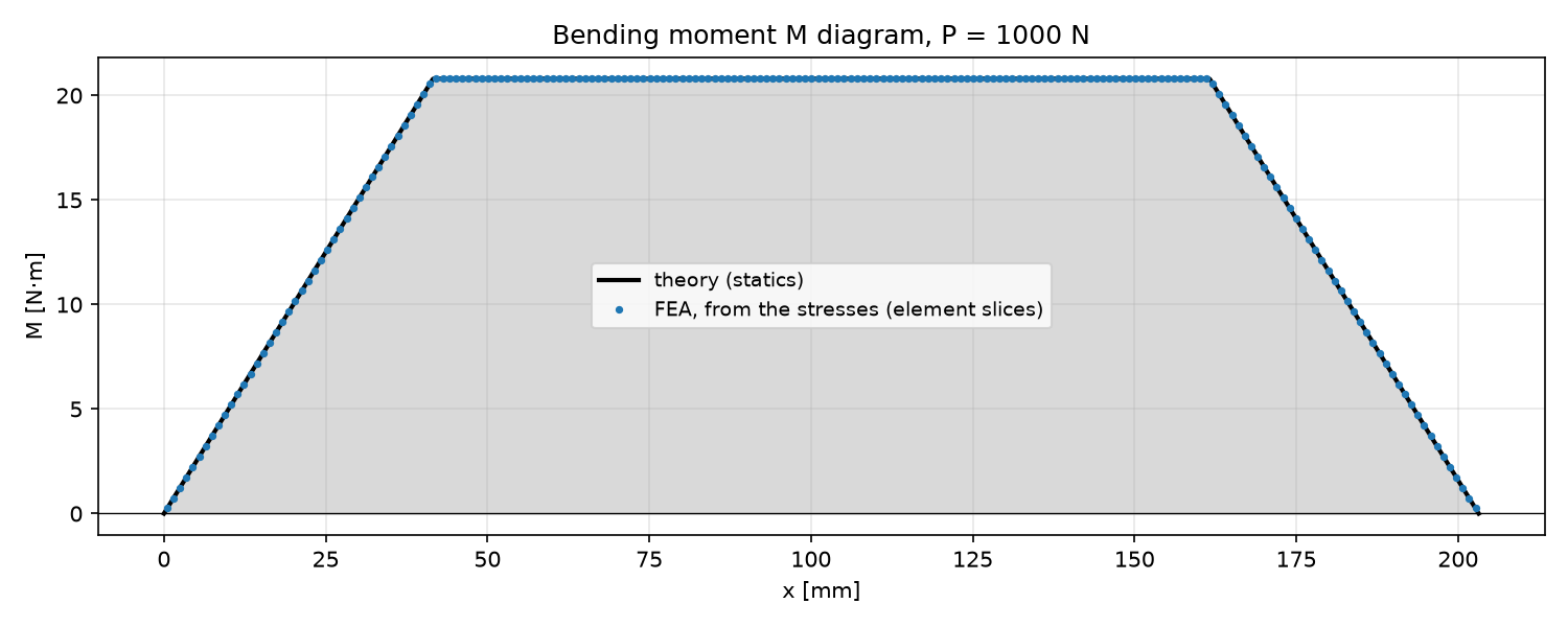
FIGURE 6. Bending moment diagram ($\mathrm{N \cdot m}$), FEA (points) against statics.
Stresses through the thickness
Figure 7 shows the stresses at mid-width through the thickness of the beam. At mid-span (left), the faces carry the moment as a couple: $\sigma_{xx} = 85.95\,\mathrm{MPa}$ on average in the bottom face, $85.65\,\mathrm{MPa}$ in theory ($+0.35\%$), and $-85.5\,\mathrm{MPa}$ in the top face; the core stress is only $\pm 0.05\,\mathrm{MPa}$. In the middle of the shear span (right), the core shear stress is nearly uniform, $1.469\,\mathrm{MPa}$ on average against $1.467\,\mathrm{MPa}$ in theory ($+0.2\%$), and it drops to zero across each face. The faces' stress in the shear span (centre) varies more through their thickness than in the theory ($44.4$ against $42.8\,\mathrm{MPa}$ on average, $+3.6\%$): they bend a little on their own, as discussed above.
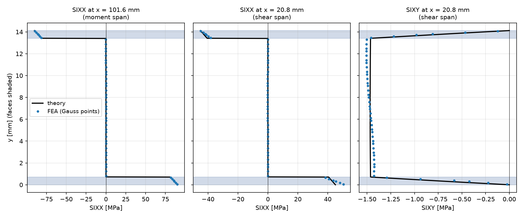
FIGURE 7. Stresses through the thickness at mid-width ($\mathrm{MPa}$, faces shaded): $\sigma_{xx}$ at mid-span ($x = 101.6\,\mathrm{mm}$) and in the shear span ($x = 20.8\,\mathrm{mm}$), and $\tau_{xy}$ in the shear span. The points are the FEA integration points, the lines the composite beam theory.
| Quantity | FEA | Theory | Difference |
|---|---|---|---|
| Reactions $R_y$ ($\mathrm{N}$) | $500.0 + 500.0$ | $500 + 500$ | $0$ |
| Shear force, shear spans ($\mathrm{N}$) | $500.00$ | $500$ | $< 0.01\%$ |
| Bending moment, moment span ($\mathrm{N \cdot m}$) | $20.800$ | $20.8$ | $< 0.01\%$ |
| Face stress at mid-span ($\mathrm{MPa}$) | $85.95$ | $85.65$ | $+0.35\%$ |
| Core shear stress, shear span ($\mathrm{MPa}$) | $1.469$ | $1.467$ | $+0.2\%$ |
| Deflection at the load points ($\mathrm{mm}$) | $1.873$ | $1.934$ | $-3.2\%$ |
| Deflection at mid-span ($\mathrm{mm}$) | $2.131$ | $2.099$ | $+1.5\%$ |
| Shear share of the deflection at the load points | $85\%$ | $85\%$ | — |
CONCLUSION
A 3D linear static finite element model of a carbon/epoxy and foam sandwich beam in 4-point flexure was built in Code_aster with a structured HEXA20 mesh and compared with sandwich beam theory. The shear force and bending moment diagrams integrated from the 3D stresses match statics exactly. The face stress and the core shear stress agree with the theory within $0.4\%$. At the loading points, the beam deflects $1.87\,\mathrm{mm}$ under $1\,\mathrm{kN}$, $3.2\%$ less than the theory, and the bending and shear parts agree within $0.5\%$ and $3.8\%$. The remaining difference is the rounding of the deflection under the loads, which the thin-face theory does not represent. The mesh is converged.
The case shows why sandwich structures need more than beam theory. The foam core makes up $85\%$ of the deflection through its shear, so a model without shear deformation would underestimate it nearly seven times. A test or a model must also deal with the local crushing of the core under line loads and supports, which here moves the beam $0.37\,\mathrm{mm}$ down on its supports, as much as its bending deflection at the load points. In a test, loading pads spread the load and the deflection is measured relative to the supports; in a model, the same correction must be made before comparing with theory. The same model gives the face and core stresses needed for failure checks (face compression, core shear, local indentation under the loads), and it can take other lay-ups, cores, spans or loading pads.
REFERENCES
- Code_aster, version 17.4.
- H. G. Allen, Analysis and Design of Structural Sandwich Panels, Pergamon Press, 1969.
- ASTM D7249/D7249M, Standard Test Method for Facesheet Properties of Sandwich Constructions by Long Beam Flexure.
- ASTM D7250/D7250M, Standard Practice for Determining Sandwich Beam Flexural and Shear Stiffness.