
Tapered Panel in Shear: Element Formulation Comparison (Cook's Membrane)
Key result: on a mesh of about one element per millimetre, linear QUAD4 and HEXA8 elements under-predict the tip deflection of Cook's membrane by about $0.6\%$ and the stress by up to $1\%$ against quadratic QUAD8 elements, and the 3D model matches the 2D plane stress model within $0.3\%$.
SUMMARY
A linear static analysis of Cook's membrane, a tapered panel clamped on one side and loaded in shear on the other [ref. 1], was performed in the finite element analysis (FEA) software Code_aster [ref. 2] with three element formulations on the same element layout: linear plane stress quadrilaterals (QUAD4), linear 3D hexahedra (HEXA8) and quadratic plane stress quadrilaterals (QUAD8). The reaction on the clamped edge balances the applied load ($-16\,000\,\mathrm{N}$) in the three models. Taking the QUAD8 model as the converged solution, the linear models give a vertical tip displacement at $P_1$ lower by $0.56\%$ (QUAD4) and $0.59\%$ (HEXA8), and a von Mises stress at $P_2$ lower by $0.75\%$ and $1.04\%$. The HEXA8 model reproduces the plane stress results within $0.3\%$, and its through-thickness strain matches the one predicted by the 2D model, which confirms that its boundary conditions do not add spurious stiffness.
INTRODUCTION
Short, deep members loaded in shear are everywhere in structures: brackets, gussets, lugs, the webs of tapered beams. In them, bending and shear act together, and this is where low-order finite elements are weakest: they tend to be too stiff, and they under-predict both the deflection and the stress.
Cook's membrane is the standard benchmark for this behaviour. There is no closed-form solution for it, so the formulations are compared with each other, with the quadratic model as the reference. Following a rigorous sequence of steps, defining the geometry, the mesh (a discretisation of the geometry), the materials and the boundary conditions, the study answers two practical questions before an element type is used on a production model: how far the linear elements are from the quadratic solution on a mesh of about one element per millimetre, and whether a 3D model of the same panel gives the same answer as the 2D plane stress model.
METHODOLOGY
A tapered panel is modeled in 2D using plane stress elements, and in 3D with its real thickness. The mechanical behavior is assumed to be linear and elastic respecting the small strain hypothesis.
Figure 1 represents the general setup of the problem. The panel is a quadrilateral defined by 4 points: $(0, 0)$, $(48, 44)$, $(48, 60)$ and $(0, 44)\,\mathrm{mm}$, with a thickness $t = 1\,\mathrm{mm}$. Its height tapers from $44\,\mathrm{mm}$ on the left edge to $16\,\mathrm{mm}$ on the right edge, and its lower and upper edges are slanted, so the panel has no symmetry. Let $P_1 = (48, 60)$ be the upper right corner, where the displacement is measured, and $P_2 = (24, 22)$ the midpoint of the lower edge, where the stress is measured.
The boundary conditions are the following. The left edge $x = 0$ is clamped, so it is blocked along $Ox$ and $Oy$. The right edge $x = 48$ carries a uniform shear traction $f_y = 1000\,\mathrm{MPa}$ along $Oy$, that is, a total force of $1000 \times 16 \times 1 = 16\,000\,\mathrm{N}$. The upper and lower edges are free.
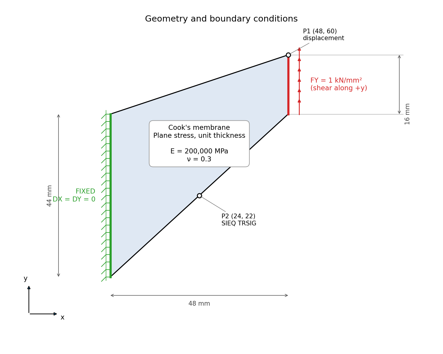
FIGURE 1. Geometry and boundary conditions of Cook's membrane in plane stress. The left edge is clamped ($u_x = u_y = 0$) and a uniform shear traction $f_y = 1000\,\mathrm{MPa}$ is applied along the right edge. $P_1$ is the displacement probe and $P_2$ the stress probe. All dimensions are in millimeters.
The material is steel, with an elastic modulus $E = 200\,000\,\mathrm{MPa}$ and a Poisson ratio $\nu = 0.3$. It is assumed to be isotropic and homogeneous, meaning that it has the same properties at every point and in all directions.
The panel is thin compared with its other dimensions and is loaded in its plane, so the stress out of the plane is zero, $\sigma_{zz} = \sigma_{xz} = \sigma_{yz} = 0$ (plane stress). The in-plane stresses and strains are then related by
$$ \begin{equation} \begin{Bmatrix} \sigma_{xx} \\ \sigma_{yy} \\ \tau_{xy} \end{Bmatrix} = \frac{E}{1-\nu^2} \begin{bmatrix} 1 & \nu & 0 \\ \nu & 1 & 0 \\ 0 & 0 & \frac{1-\nu}{2} \end{bmatrix} \begin{Bmatrix} \varepsilon_{xx} \\ \varepsilon_{yy} \\ \gamma_{xy} \end{Bmatrix} \end{equation} $$
The strain out of the plane is not zero. The panel gets thinner where it is stretched and thicker where it is compressed:
$$ \begin{equation} \varepsilon_{zz} = -\frac{\nu}{E} \left( \sigma_{xx} + \sigma_{yy} \right). \end{equation} $$
With a static load and no body forces, the equilibrium equations are
$$ \begin{equation} \sigma_{ij,j} = 0 \quad , \quad i = x,y \end{equation} $$
with summation over the repeated index $j$, together with $u_x = u_y = 0$ on the clamped edge, $\sigma_{xy} = f_y$ and $\sigma_{xx} = 0$ on the loaded edge, and zero traction on the free edges.
Why are linear finite elements too stiff in bending?
The panel works essentially as a short cantilever in bending. In pure bending, the fibres parallel to the axis stretch or shorten linearly across the height, and the sides of an element rotate but remain straight. A four-node quadrilateral has a bilinear displacement field: its sides stay straight, but it cannot bend them into the curved shape of a bent fibre. To follow the bending, the element distorts in shear instead, and this shear strain does not exist in the real panel (parasitic shear). It stores strain energy that the real panel does not, so the element is stiffer than the material it represents [ref. 3]. The effect decreases as the mesh is refined, and it grows when the element is distorted from a rectangle. Eight-node quadrilaterals have quadratic sides and represent bending almost exactly, so they are used here as the reference.
Models. Three models were solved, all with the same element layout in the plane of the panel:
| Model | Formulation | Code_aster modelling | Elements | Nodes |
|---|---|---|---|---|
| a | 2D plane stress, linear | C_PLAN | 1860 QUAD4 | 1953 |
| b | 3D, 2 layers through the thickness | 3D | 3720 HEXA8 | 5859 |
| c | 2D plane stress, quadratic | C_PLAN | 1860 QUAD8 | 5765 |
In model b, the clamped face is blocked along $Ox$ and $Oy$, and along $Oz$ only on its mid-thickness line. This removes the rigid-body motion along $z$ without restraining the Poisson thinning of equation $(2)$, so the conditions match those of the plane stress models. Clamping the whole face along $z$ would prevent the panel from changing thickness at the support and add a stiffness that the 2D models do not have. The two layers put a row of nodes on the mid-plane $z = t/2$, where the results are read.
Mesh. The geometry was discretised with a structured mesh of 1860 quadrilaterals, 62 columns by 30 rows, generated with Gmsh, plus 60 SEG2 edge elements carrying the boundary conditions and the load. Because the panel height shrinks from $44\,\mathrm{mm}$ to $16\,\mathrm{mm}$, the element height shrinks from $1.47\,\mathrm{mm}$ to $0.53\,\mathrm{mm}$; the column width follows a geometric progression, from $1.22\,\mathrm{mm}$ on the left to $0.45\,\mathrm{mm}$ on the right, so that the elements stay close to square in size across the panel. The edge aspect ratio is close to 1 everywhere (mean 1.08, maximum 1.15), and the corner Jacobian ratio is 0.98 in every element, so no element is folded or badly tapered. The skew, measured as the largest deviation of an interior angle from $90^\circ$, is higher than in the other cases: $32^\circ$ on average, $43^\circ$ at most. It is imposed by the geometry, because the rows follow the slanted lower and upper edges, so each element is nearly a parallelogram leaning with the panel. This distortion is part of the benchmark: it is precisely what makes Cook's membrane demanding for linear elements. Models b and c use the same layout: model b extrudes it into 2 layers of HEXA8 elements, and model c adds a mid-side node on every edge (QUAD8), as shown in figure 2.
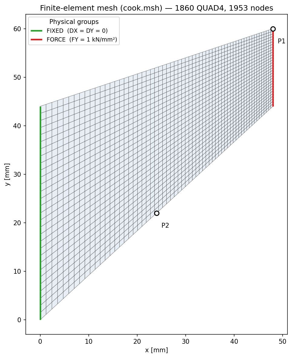
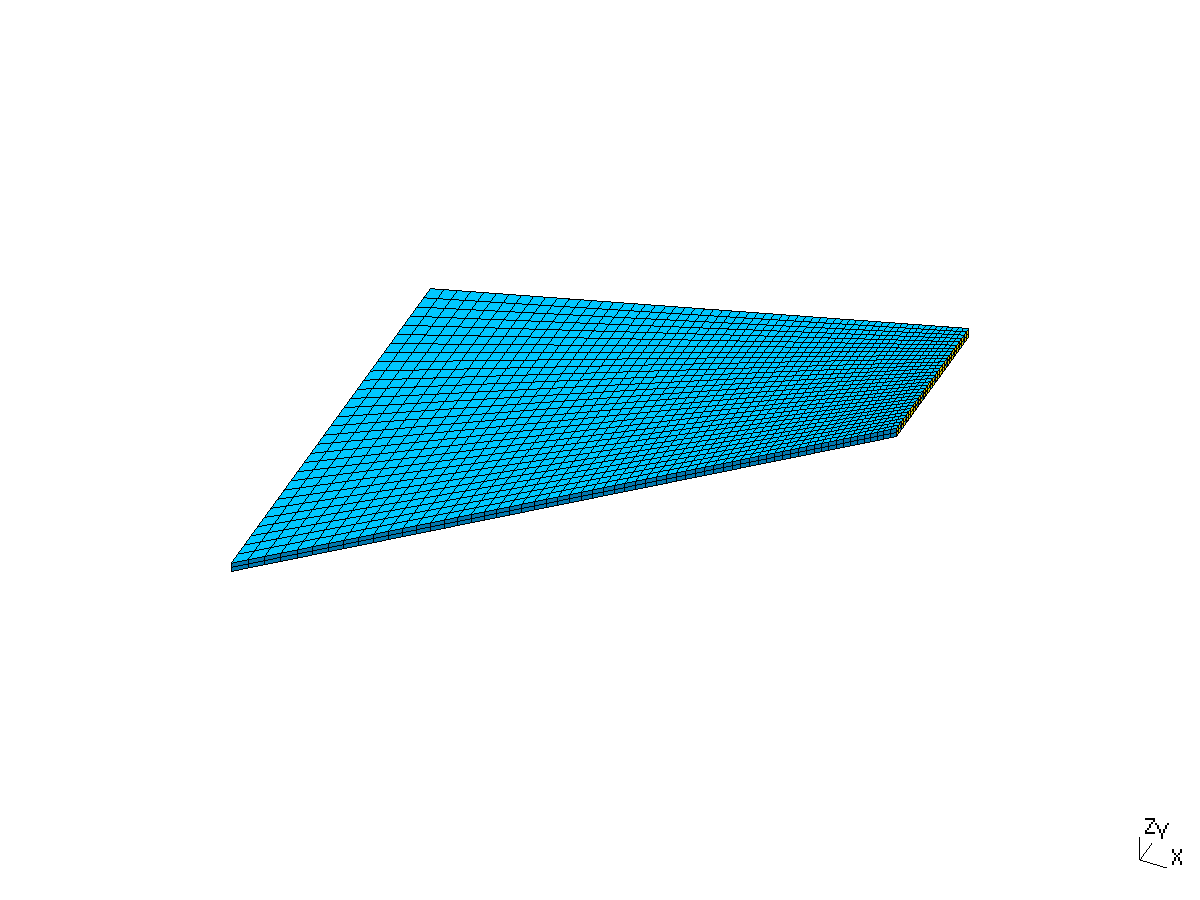
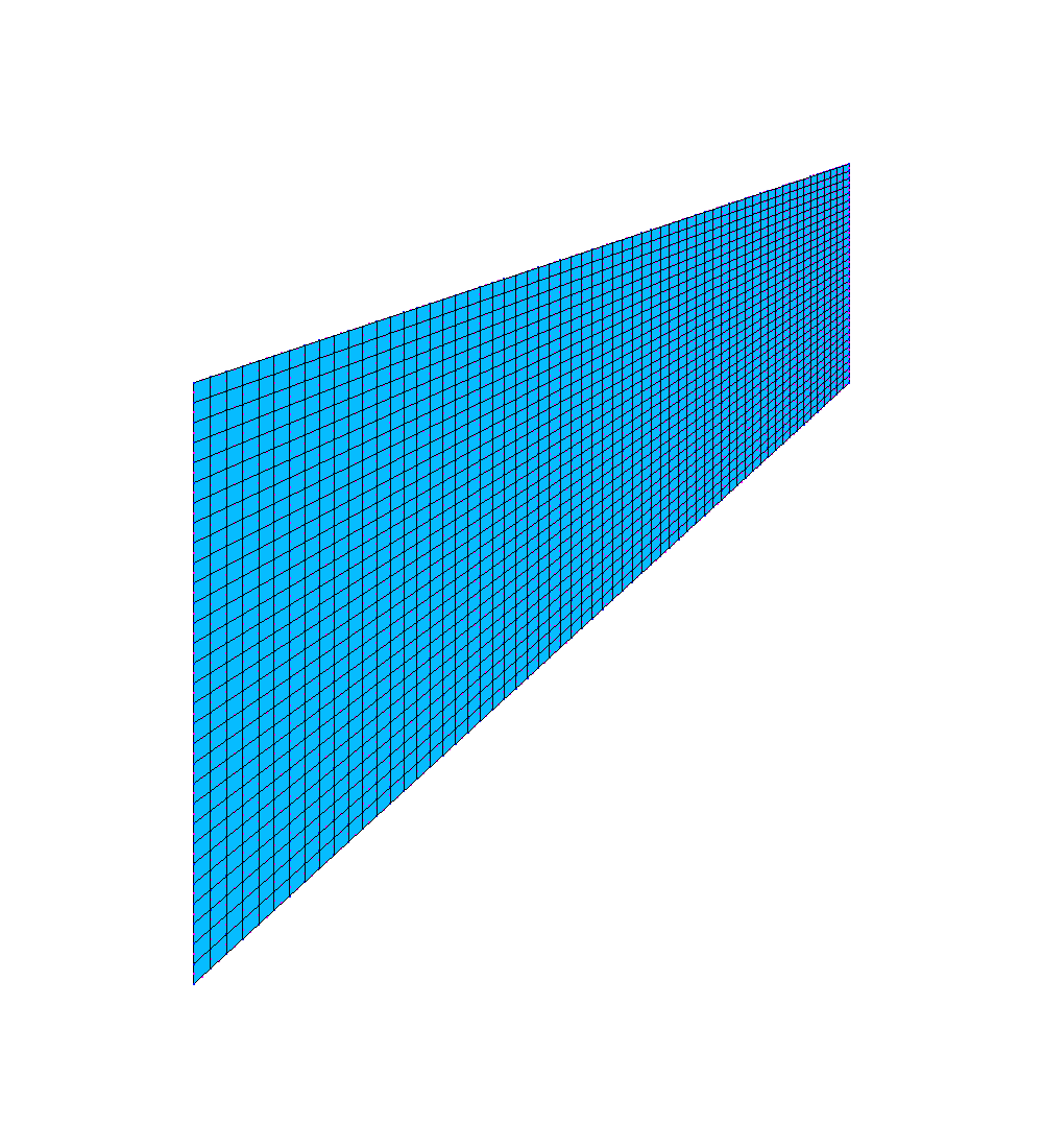
FIGURE 2. Finite element meshes, with the same element layout: (a) model a, 1860 QUAD4 elements and 1953 nodes, with the element groups used for the boundary conditions; (b) model b, 3720 HEXA8 elements in 2 layers through the thickness; (c) model c, 1860 QUAD8 elements and 5765 nodes.
Result extraction. $P_1$ is a node in all three models. $P_2$ is not a node of the linear meshes: it lies on the lower edge between two nodes, $0.57\,\mathrm{mm}$ from each. The stress at $P_2$ is therefore interpolated from the nodal stress field with MACR_LIGN_COUPE, in all three models, and read at mid-thickness in model b.
RESULTS
The reaction on the clamped edge is $R_y = -16\,000\,\mathrm{N}$ in the three models, equal to the applied load, so the models are in equilibrium. The horizontal reaction is zero to within $10^{-8}\,\mathrm{N}$, and in model b the out-of-plane reaction of the mid-thickness line is below $10^{-9}\,\mathrm{N}$: the $u_z = 0$ condition removes the rigid-body motion without carrying any load.
Figure 3 shows the magnitude of the displacement on the deformed shape of model c. The panel bends upward as a cantilever: the displacement grows from zero on the clamped edge to its maximum at the upper right corner $P_1$, $2.514\,\mathrm{mm}$, of which $u_y = 2.0086\,\mathrm{mm}$ and $u_x = -1.5111\,\mathrm{mm}$. The horizontal component is large because $P_1$ is on the upper edge, far from the mid-line of the panel, and the right edge rotates as the panel bends.
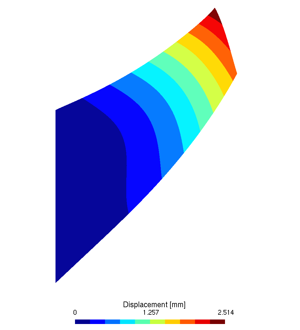
FIGURE 3. Displacement magnitude ($\mathrm{mm}$), model c, on the deformed shape. The maximum is at the upper right corner $P_1$.
Figure 4 shows the equivalent von Mises stress of model c. As in a cantilever, the stress is highest along the lower and upper edges, where the bending fibres stretch and shorten the most, and lowest along a band in the middle of the panel, near the neutral axis. The lower edge is in tension and the upper edge in compression. At $P_2$, on the lower edge, $\sigma_{VM} = 3790.4\,\mathrm{MPa}$.
The peak value, $9084\,\mathrm{MPa}$, is at the upper left corner $(0, 44)$, where the clamped edge meets the free upper edge at an angle of $108^\circ$. For a clamped–free corner wider than about $63^\circ$, the elastic solution is singular: the stress there is infinite in theory [ref. 4], and in the model it grows with the mesh refinement and the element order ($8148\,\mathrm{MPa}$ with QUAD4, $8128\,\mathrm{MPa}$ with HEXA8, $9084\,\mathrm{MPa}$ with QUAD8). It is not a design value. At the lower left corner, the angle is $47^\circ$, below the limit, and the stress there stays low.
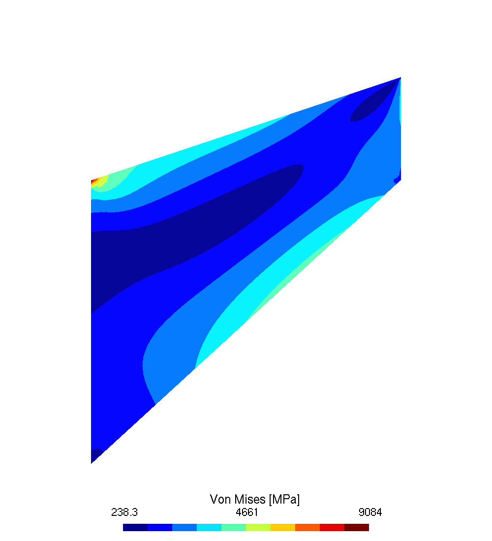
FIGURE 4. Equivalent von Mises stress ($\mathrm{MPa}$), model c. The peak value ($9084\,\mathrm{MPa}$) is at the upper left clamped corner, where the elastic solution is singular.
The table compares the three models. The linear models are stiffer than the quadratic one, as expected from the parasitic shear: model a gives a vertical displacement at $P_1$ of $\tilde{u}_y = 1.9974\,\mathrm{mm}$, $0.56\%$ lower than the $2.0086\,\mathrm{mm}$ of model c, and a stress at $P_2$ of $\tilde{\sigma}_{VM} = 3761.8\,\mathrm{MPa}$, $0.75\%$ lower than the $3790.4\,\mathrm{MPa}$ of model c. The horizontal displacement shows the same trend, $0.81\%$ lower. Model b is within $0.03\%$ of model a on the displacement and within $0.3\%$ on the stress: the 3D linear element behaves like the 2D one.
| Quantity | a: QUAD4 | b: HEXA8 | c: QUAD8 |
|---|---|---|---|
| Reaction $R_y$ ($\mathrm{N}$) | $-16\,000$ | $-16\,000$ | $-16\,000$ |
| $u_x$ at $P_1$ ($\mathrm{mm}$) | $-1.4988$ | $-1.4983$ | $-1.5111$ |
| $u_y$ at $P_1$ ($\mathrm{mm}$) | $1.9974$ | $1.9968$ | $2.0086$ |
| von Mises at $P_2$ ($\mathrm{MPa}$) | $3761.8$ | $3751.1$ | $3790.4$ |
| Tresca at $P_2$ ($\mathrm{MPa}$) | $3829.1$ | $3805.4$ | $3790.5$ |
| $u_x$ difference vs c | $-0.81\%$ | $-0.85\%$ | — |
| $u_y$ difference vs c | $-0.56\%$ | $-0.59\%$ | — |
| von Mises difference vs c | $-0.75\%$ | $-1.04\%$ | — |
The Tresca stress gives a further check of the stress at $P_2$. On a free edge, the only non-zero stress is the one along the edge, so the stress state is uniaxial and the von Mises and Tresca stresses must be equal. In model c, they agree within $0.003\%$ ($3790.4$ against $3790.5\,\mathrm{MPa}$). In the linear models, they differ by $1.8\%$ (model a) and $1.4\%$ (model b): the linear elements recover the stress less accurately on the edge, where it is extrapolated from the Gauss points to the nodes and averaged.
In model b, the faces of the panel move out of plane by up to $\pm 0.0087\,\mathrm{mm}$, at the upper left corner. This is the Poisson thinning of equation $(2)$, which the plane stress models compute but do not display as a displacement: model a gives $\varepsilon_{zz} = 0.0177$ at the same corner, that is, $\varepsilon_{zz} \, t/2 = 0.0088\,\mathrm{mm}$ on each face, within $1.3\%$ of the 3D model. The through-thickness behaviour of the 3D model is therefore that of a free plate in plane stress.
CONCLUSION
A linear static finite element analysis of Cook's membrane was performed in Code_aster with three element formulations, with the goal of quantifying how much linear elements under-predict the deflection and the stress of a panel in combined bending and shear, and whether a 3D model reproduces the 2D plane stress model. All three models are in equilibrium and agree within about $1\%$. On this mesh, of about one element per millimetre, the linear elements are slightly too stiff: they under-predict the tip deflection by about $0.6\%$ and the stress at $P_2$ by up to $1\%$, compared with the quadratic solution, despite the skew of about $30^\circ$ imposed by the geometry. The 3D model matches the 2D plane stress model within $0.3\%$, and its through-thickness strain matches the one predicted in plane stress, so the choice between the two can be made on cost, not accuracy.
The stress at the upper clamped corner is singular: it grows with the mesh and the element order, and must not be read as an allowable-stress check. With a shear traction of $1000\,\mathrm{MPa}$, the stresses reach about $3800\,\mathrm{MPa}$ and the strains about $4\%$ near the corner, far beyond the elastic range of steel; the load is a scaled version of the classical unit-load benchmark, and since the analysis is linear, all the results scale directly with it. On a real part, a stress check at this level would require an elastoplastic analysis, and the same workflow extends to it directly.
REFERENCES
- R. D. Cook, Improved two-dimensional finite element, Journal of the Structural Division, ASCE, 100(ST9), 1974, pp. 1851-1863.
- Code_aster, version 15.2.
- R. D. Cook, D. S. Malkus, M. E. Plesha, R. J. Witt, Concepts and Applications of Finite Element Analysis, 4th ed., J. Wiley, 2002.
- M. L. Williams, Stress singularities resulting from various boundary conditions in angular corners of plates in extension, Journal of Applied Mechanics 19, 1952, pp. 526-528.