
Loaded Pin in a Bore: Frictional Contact Verification (NAFEMS)
Key result: Code_aster reproduces the NAFEMS loaded-pin contact benchmark: the displacement at the contact point is within $0.56\%$ of the reference with linear elements ($0.7220\,\mathrm{mm}$ vs $0.7180\,\mathrm{mm}$) and within $0.43\%$ with quadratic elements, and the stress there within $3.0\%$ and $1.3\%$ respectively.
SUMMARY
A nonlinear static analysis of a steel pin pushed against the bore of an aluminium console, with Coulomb friction, was performed as a validation of the contact formulation of the finite element analysis (FEA) software Code_aster, following its validation case SSNP156 [ref. 1], itself taken from the NAFEMS contact benchmarks [ref. 2]. With linear elements (QUAD4), the FEA model gives a horizontal displacement at the contact point $A$ of $u_x = 0.7220\,\mathrm{mm}$ against $0.7180\,\mathrm{mm}$ in the reference, a difference of $0.56\%$, and a stress $\sigma_{xx} = -140.8\,\mathrm{MPa}$ against $-136.7\,\mathrm{MPa}$, a difference of $3.0\%$. A second model with quadratic elements (QUAD8) reduces the differences to $0.43\%$ and $1.3\%$, respectively. The tolerances of the validation case ($0.45\%$ on the displacement, $0.07\%$ on the stress) are set for its own reference mesh, not for an independent mesh like the one used here.
INTRODUCTION
Pins in holes are everywhere in structures: lugs, clevises, hinges, bolted joints. When the pin is loaded, it bears on one side of the hole and lifts off the other, and the load passes through a contact arc whose extent is not known in advance.
This makes the problem nonlinear, even with linear elastic materials and small displacements. There is no closed-form solution for a pin in a hole of finite size, so the reference is the NAFEMS benchmark, an average of several commercial codes, reproduced by the Code_aster validation case. Following a rigorous sequence of steps, defining the geometry, the mesh (a discretisation of the geometry), the materials, the boundary conditions and the contact, the model should recover the displacement and the stress at the point where the pin bears hardest on the hole. The objective is to recover both, with linear and quadratic elements, and to check the contact settings (formulation, master and slave surfaces, friction, load stepping) before applying them to a real joint.
METHODOLOGY
A console with a pin in its bore is modeled in 2D using plane strain elements. The mechanical behavior is assumed to be linear and elastic respecting the small strain hypothesis. The only nonlinearity is the contact between the pin and the console.
Figure 1 represents the general setup of the problem. The console is a rectangle of $200\,\mathrm{mm}$ by $100\,\mathrm{mm}$, extended on its right by a half disc of radius $100\,\mathrm{mm}$. The pin, of radius $R = 50\,\mathrm{mm}$, sits in a hole of the same radius, centred at $F = (200, 0)$, with no initial gap. Since the geometry and the load are symmetric about the $x$ axis, only one half is modeled. Let $A = (250, 0)$ be the point of the hole edge on the load line, where the pin bears on the console.
The boundary conditions are the following. The left edge of the console is clamped, so it is blocked along $Ox$ and $Oy$. The bottom edge $y = 0$ is the symmetry plane, so it is blocked along $Oy$. A force $F_x = 10\,000\,\mathrm{N}$ (half model) is applied at the pin centre $F$ along $Ox$, pushing the pin against the hole towards $A$.
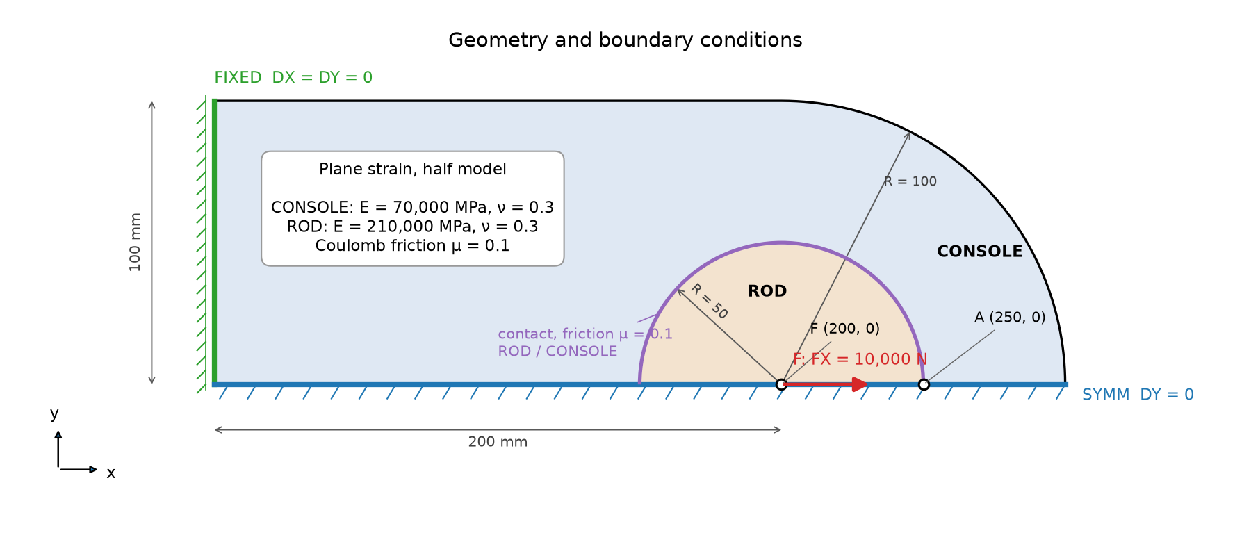
FIGURE 1. Geometry, boundary conditions and point $A$ of the half model of the pin in the console, in plane strain. The console is clamped on its left edge ($u_x = u_y = 0$) and the symmetry condition is applied along $y = 0$ ($u_y = 0$). A force $F_x = 10\,000\,\mathrm{N}$ is applied at the pin centre $F$. The pin and the hole are in frictional contact ($\mu = 0.1$). All dimensions are in millimeters.
The console is aluminium and the pin is steel. Both materials are assumed to be isotropic and homogeneous, meaning that they have the same properties at every point and in all directions.
| Part | Material | $E$ ($\mathrm{MPa}$) | $\nu$ |
|---|---|---|---|
| Console | aluminium | $70\,000$ | 0.3 |
| Pin (rod) | steel | $210\,000$ | 0.3 |
In plane strain, the strain out of the plane is zero, $\varepsilon_{zz} = 0$. The out-of-plane stress is therefore not zero, but
$$ \begin{equation} \sigma_{zz} = \nu \left( \sigma_{xx} + \sigma_{yy} \right). \end{equation} $$
Inside each body, the equilibrium equations are the same as for any static problem without body forces,
$$ \begin{equation} \sigma_{ij,j} = 0 \quad , \quad i = x,y \end{equation} $$
with summation over the repeated index $j$. What changes is the interface. Let $g_n$ be the normal gap between the pin and the hole, $p_n$ the contact pressure (positive in compression) and $\boldsymbol{t}$ the tangential traction. At every point of the interface, the pin and the hole cannot interpenetrate, and they can only push on each other, never pull (Signorini conditions):
$$ \begin{equation} g_n \geq 0 \quad , \quad p_n \geq 0 \quad , \quad g_n \, p_n = 0 \end{equation} $$
Either the gap is open and there is no pressure, or the gap is closed and there is pressure. Where the surfaces touch, the friction follows Coulomb's law,
$$ \begin{equation} \| \boldsymbol{t} \| \leq \mu \, p_n \end{equation} $$
with $\mu = 0.1$. Below the limit, the surfaces stick. At the limit, they slide, and the friction opposes the sliding. Which points are open, which stick and which slide is part of the solution, and this is what makes the problem nonlinear.
How is frictional contact modeled in Code_aster?
Contact. In Code_aster, the conditions $(3)$ and $(4)$ are enforced with the continuous (CONTINUE) formulation, in which the contact pressure is an unknown of the problem (the Lagrange multiplier LAGS_C). The contact status, the friction and the geometry are all solved by Newton's method. The hole surface is the master and the pin surface is the slave. The interface nodes were duplicated so that the pin and the console have matching but independent meshes. The load was applied in 5 equal increments, with automatic subdivision of the step in case of failure; it was never needed.
Mesh. The geometry was discretised twice with the same 1271 quadrilateral elements: model A with linear QUAD4 elements (1382 nodes, SEG2 contact edges) and model B with quadratic QUAD8 elements (4033 nodes, SEG3 contact edges). The counts include the 37 (model A) and 73 (model B) duplicated interface nodes. Around the pin the mesh is a ring of radial, graded elements, with 36 element edges along the half circumference of the contact surface, about $4.4\,\mathrm{mm}$ each. Inside the pin and away from it, the mesh becomes a block-structured coarser grid. The mesh quality is good. The edge aspect ratio is close to 1 (mean 1.17, maximum 1.51), and the corner Jacobian ratio is at least 0.85 (mean 0.99), so no element is folded or badly tapered. The skew, measured as the largest deviation of an interior angle from $90^\circ$, averages $7^\circ$ and is below $10^\circ$ in $80\%$ of the elements. The most distorted elements (maximum $45^\circ$, 8 elements above $40^\circ$) lie at the corners of the inner square of the pin, about $17\,\mathrm{mm}$ from its centre, and in the console block on the side of the pin that lifts off. None of them touch the contact arc. The ring elements along the interface, where the contact is evaluated, are almost perfect squares (aspect ratio below 1.27, skew below $5^\circ$), as shown in figure 2.
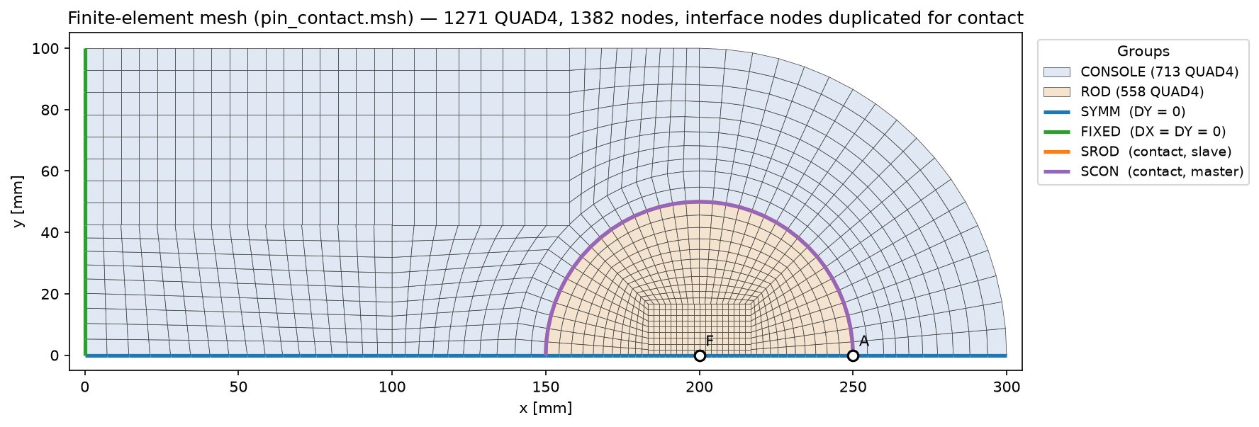
FIGURE 2. Finite element mesh of model A (QUAD4), with the element groups used for the boundary conditions and the contact.
In model B, the contact terms are integrated at 4 Gauss points per edge instead of at the nodes. On quadratic edges, a nodal integration makes the contact pressure oscillate between the corner and the mid-side nodes; the Gauss integration damps it.
Reference. The reference values at $A$ are those of the Code_aster validation case [ref. 1]: $u_x = 0.7180\,\mathrm{mm}$ and $\sigma_{xx} = -136.7\,\mathrm{MPa}$ for its linear model, and $u_x = 0.7362\,\mathrm{mm}$ and $\sigma_{xx} = -160.4\,\mathrm{MPa}$ for its quadratic model. Its tolerances are $0.45\%$ on $u_x$ and $0.07$ to $0.08\%$ on $\sigma_{xx}$. They are tight because they check Code_aster against itself, on its own 820-element mesh; the NAFEMS benchmark [ref. 2] behind it is an average of commercial codes, with a much larger scatter.
RESULTS
The reaction on the clamped edge is $R_x = -10\,000\,\mathrm{N}$ in both models, equal to the applied force, so the models are in equilibrium. Both models converged in the 5 increments, without subdivision. The response is proportional to the load: the displacement of the pin centre and the contact pressure at $A$ grow linearly with it, within $0.3\%$. This is expected, because the initial gap is zero and the materials are linear, so the contact arc does not change with the load, only the magnitudes do.
Figure 3 shows the magnitude of the displacement across the model. The pin moves almost as a rigid body, with its maximum at the centre $F$: $u_x = 0.8488\,\mathrm{mm}$. The console deforms around the contact arc, and its displacement decays from the hole edge to zero on the clamped edge.
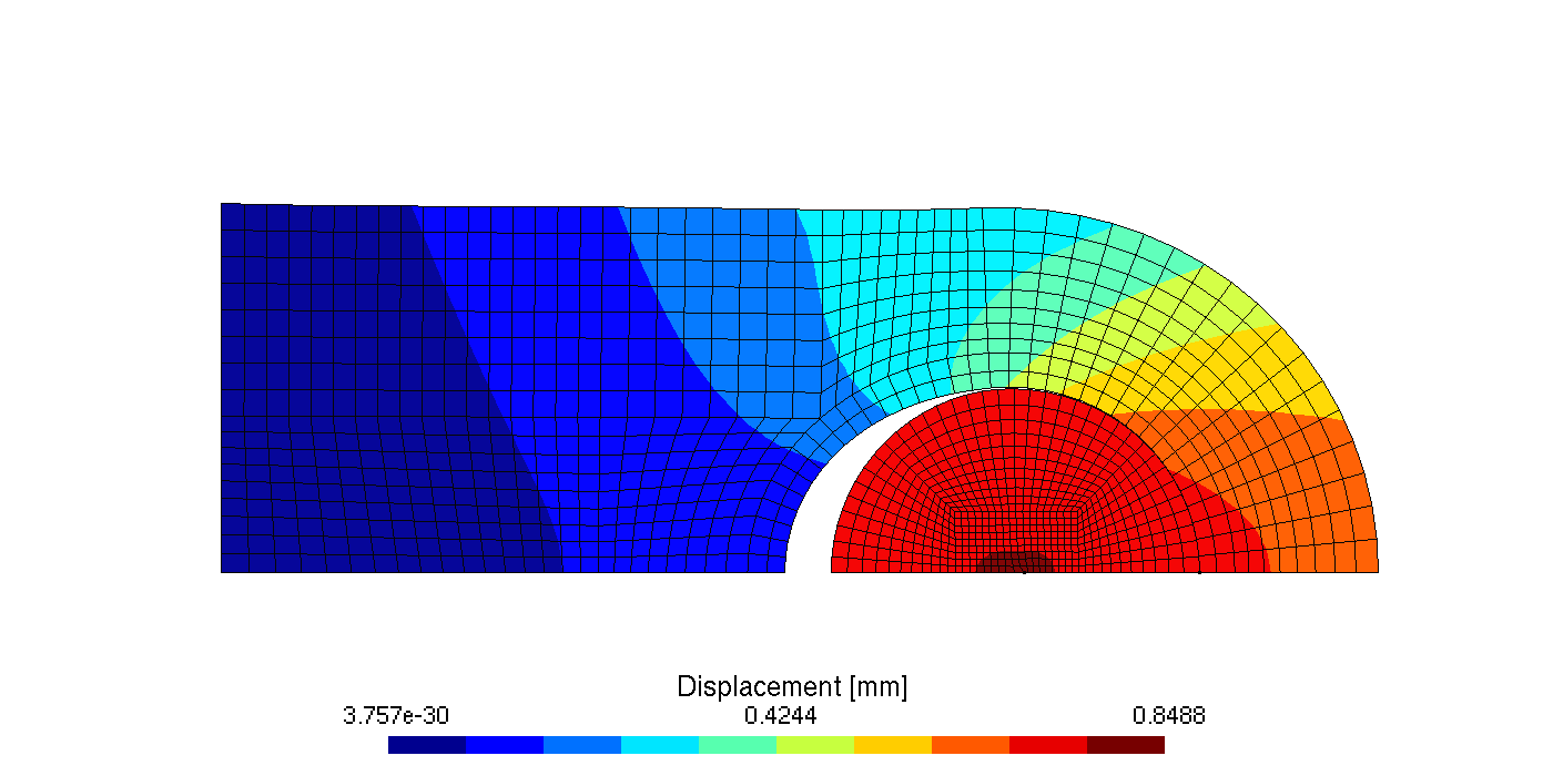
FIGURE 3. Displacement magnitude ($\mathrm{mm}$), model A. The maximum is in the pin; the console displacement is zero on the clamped edge.
Figure 4 shows the contact pressure along the pin, from the far side of the hole ($0^\circ$) to $A$ ($180^\circ$). The pin is in contact from about $90^\circ$ to $180^\circ$, that is, over the whole quarter facing the load, and open over the other quarter. The pressure peaks at $208.7\,\mathrm{MPa}$ near $115^\circ$, not at $A$, and falls to $142.2\,\mathrm{MPa}$ at $A$. Integrating the pressure along the arc, its horizontal component carries $8721\,\mathrm{N}$ of the $10\,000\,\mathrm{N}$ load; friction carries the rest, about $13\%$.
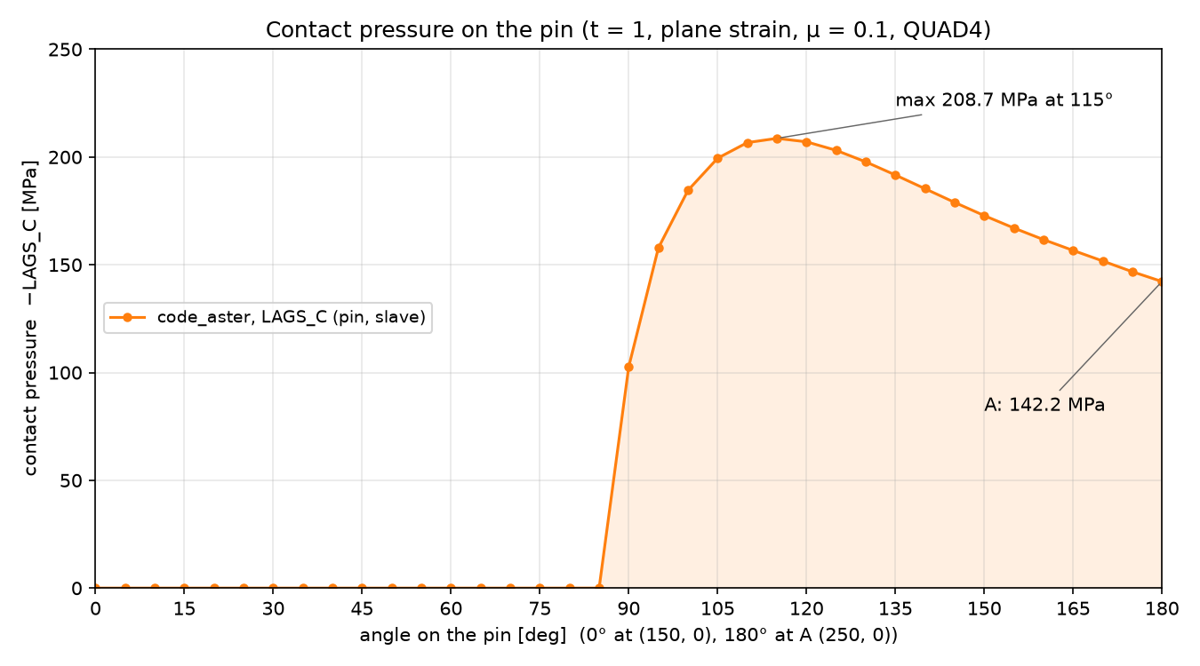
FIGURE 4. Contact pressure along the pin ($\mathrm{MPa}$), model A. The pin is in contact from about $90^\circ$ to $180^\circ$ ($A$); the maximum is $208.7\,\mathrm{MPa}$ near $115^\circ$.
Figure 5 shows the horizontal displacement of both surfaces along the interface, for both models. Over the contact arc, from about $90^\circ$ to $180^\circ$, the pin and the hole move together and the normal gap is closed. Over the other quarter, the pin moves away from the hole edge and the gap opens, up to $0.63\,\mathrm{mm}$ (model A) and $0.65\,\mathrm{mm}$ (model B) on the far side. The contact conditions $(3)$ are respected: where the gap is open the pressure is zero (Figure 4), and where the pressure is not zero the gap is closed. Model B closes it more tightly: the residual gap on the arc is below $1.2\,\mathrm{\mu m}$, against up to $12\,\mathrm{\mu m}$ in model A near $90^\circ$, where the linear edges cut across the curved hole.
The two models differ mainly by a shift of the pin. The pin surface of model B moves $17$ to $22\,\mathrm{\mu m}$ further than in model A all along the interface, the most near $100^\circ$, as the stiffer QUAD4 elements underestimate its displacement. The hole edge agrees within $1.3\,\mathrm{\mu m}$ over the open side; on the contact arc, where it is carried by the pin, the difference grows to $17\,\mathrm{\mu m}$ at $A$, the same as for the pin. The contact arc itself barely changes: it starts at $87.5^\circ$ in model B and $90^\circ$ in model A.
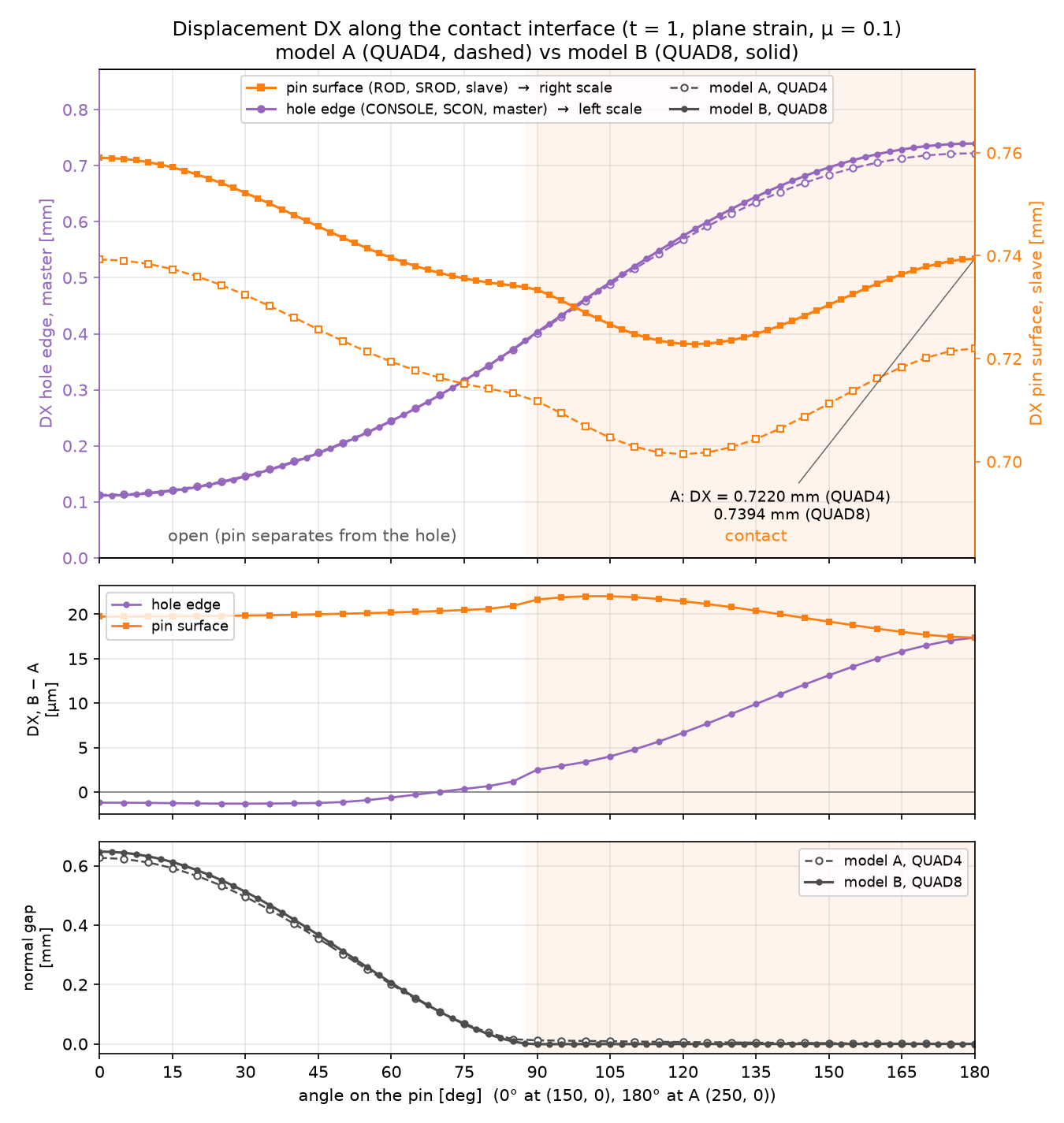
FIGURE 5. Horizontal displacement of the pin and hole surfaces along the interface (top), difference between models B and A (middle) and normal gap (bottom). Model A (QUAD4) is dashed, model B (QUAD8) solid. The shaded area is the contact arc.
Figure 6 shows the equivalent von Mises stress. In the console, the stress concentrates along the contact arc, where the pin bears on the hole, with its highest values where the contact pressure peaks. The stress at the pin centre exceeds the scale of the figure, but it is a local artefact of the point load: a force applied at a single node gives an infinite stress in theory, and a mesh-dependent one in the model. It has no effect on the results at $A$, $50\,\mathrm{mm}$ away.
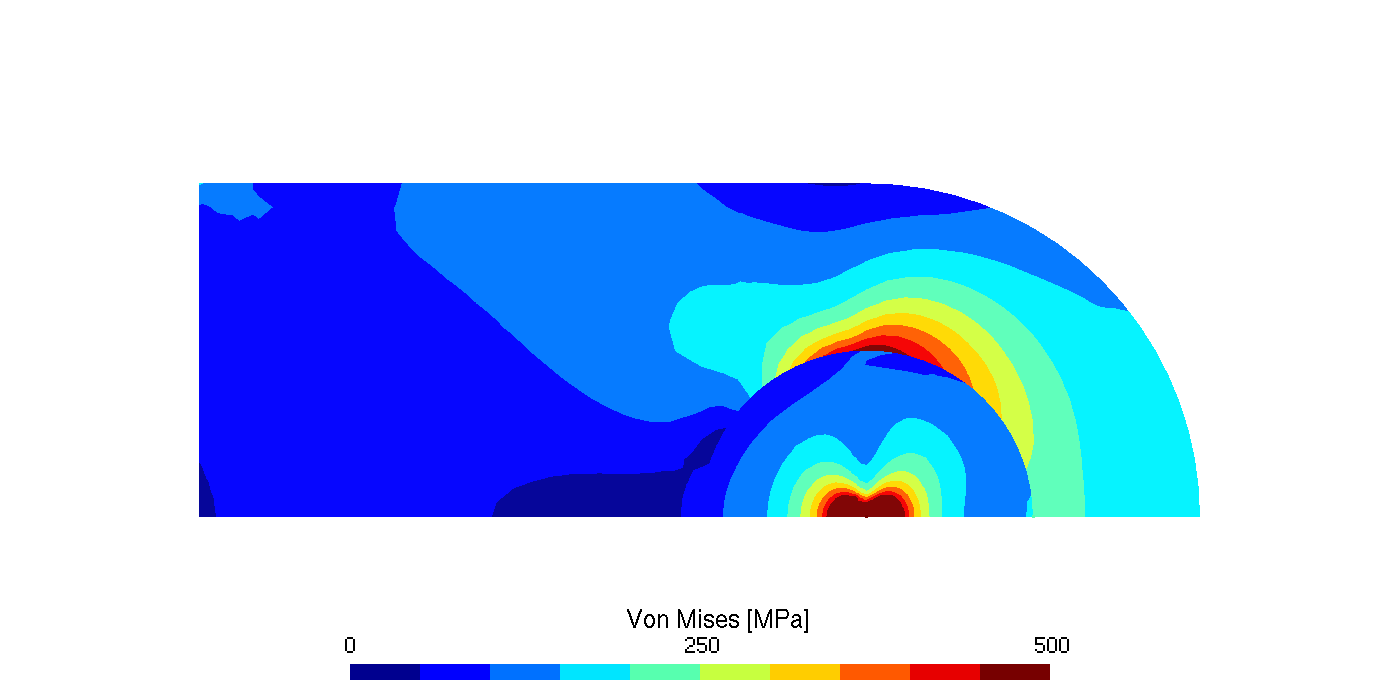
FIGURE 6. Von Mises stress ($\mathrm{MPa}$), model A, with the scale capped at $500\,\mathrm{MPa}$. The peak at the pin centre is an artefact of the point load.
The table compares the results at $A$ with the reference. In model A, the displacement is $\tilde{u}_x = 0.7220\,\mathrm{mm}$, a relative error of $0.56\%$ against the reference value $u_x = 0.7180\,\mathrm{mm}$. The stress is $\tilde{\sigma}_{xx} = -140.8\,\mathrm{MPa}$, meaning that this area is in compression, a relative error of $3.0\%$ against the reference value $\sigma_{xx} = -136.7\,\mathrm{MPa}$. In model B, the errors drop to $0.43\%$ on the displacement, within the tolerance, and $-1.3\%$ on the stress. The contact pressure at $A$ is consistent with the stress: $142.2\,\mathrm{MPa}$ against $|\sigma_{xx}| = 140.8\,\mathrm{MPa}$ in model A, and $156.7\,\mathrm{MPa}$ against $158.3\,\mathrm{MPa}$ in model B. The out-of-plane stress also follows equation $(1)$: in model A, $\sigma_{zz} = 0.3 \times (-140.8 + 92.5) = -14.5\,\mathrm{MPa}$, the value computed by Code_aster.
| Quantity at $A$ | Reference | A: QUAD4 | Difference | B: QUAD8 | Difference | Tolerance |
|---|---|---|---|---|---|---|
| $u_x$ ($\mathrm{mm}$) | $0.7180$ / $0.7362$ | $0.7220$ | $+0.56\%$ | $0.7394$ | $+0.43\%$ | $0.45\%$ |
| $\sigma_{xx}$ ($\mathrm{MPa}$) | $-136.7$ / $-160.4$ | $-140.8$ | $+3.0\%$ | $-158.3$ | $-1.3\%$ | $0.07$ to $0.08\%$ |
| Contact pressure ($\mathrm{MPa}$) | $142.2$ | $156.7$ |
The reference values are those of the linear / quadratic models of the validation case respectively.
CONCLUSION
A two-dimensional nonlinear static finite element analysis of a steel pin pushed against the bore of an aluminium console, with Coulomb friction, was performed in Code_aster, with the goal of reproducing the NAFEMS loaded-pin benchmark. Code_aster reproduces it: with linear elements, the displacement at $A$ is within $0.56\%$ of the reference, and within the tolerance with quadratic elements, the contact arc and the gap follow the contact conditions, and the contact pressure at $A$ agrees with the stress there. The stress at $A$ is more sensitive to the mesh: it moves from $+3.0\%$ with QUAD4 to $-1.3\%$ with QUAD8. It is outside the tolerance of the validation case, which is set for its own mesh, but well within the scatter of the commercial codes behind the benchmark.
When contact stresses drive the design of a joint, quadratic elements, or a finer linear mesh along the contact arc, should be used. The peak contact pressure is not at the load line but about $65^\circ$ off it, which is where the bearing stress should be checked. The same workflow extends directly to the cases this benchmark leaves out: a clearance between the pin and the hole, and plastic material behaviour at the contact edge.
REFERENCES
- Code_aster validation case SSNP156
- A. Konter, Advanced Finite Element Contact Benchmarks, NAFEMS, 2006.